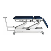
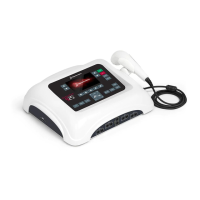
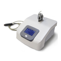
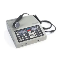
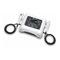
Dynatron® 850plus & 550plus
Schematics and QC Check Lists
DS005C - REV 6 – 10/25/02
130
DYNATRON 650/550 PLUS and PLUS E FINAL QUALITY CHECK
Unit S/N__________________ Software Ver._____ Date__/__/__ TECH/QC
epair_____RS_____Production____
(Initials)
1. Verify all LED’s light, all key presses function and have [ ] [ ]
good tactile feel.
2. INTERFERENTIAL: 42-55 Vpp [ ] [ ]
a) Static- High/Low (all channels) ± 4Vpp
b) Target/ Sweep (all channels)
c) Modify Features (mode, time, function, cancel)
d) Verify current limit 50 mA maximum
3. PREMODULATED 42-55 Vpp [ ] [ ]
a) High/Low (all channels)
b) High/Low alternate (all channels)
c) Modify Features (mode, time, cancel)
d) Verify current limit 50 mA maximum
4. RUSSIAN STIM: 42-55 Vpp [ ] [ ]
a) One Channel Normal (all channels)
b) Two Channel Reciprocal (channel pairs)
c) Two Channel Co-contraction (channel pairs)
d) Verify current limit 50 mA maximum
5. BI-PHASIC: 42-55 Vpp [ ] [ ]
a) One Channel Normal (all channels)
b) Two Channel Reciprocal (channel pairs)
c) Two Channel Co-contraction (channel pairs)
d) Verify current limit 50 mA maximum
6. CHECK: labels, screws, chime, jacks, remote stop [ ] [ ]
micro probe conductance.
7. FUSE check rating (1.6/0.8 Amp slow-blow 250v) [ ] [ ]
8. VERIFY: [ ] [ ]
a) Custom Presets
b) Check Lead Test, (target/sweep upon power up or function target after power up)
c) Check lead warning
d) Conductance bar graph
e) Labels
9. Microcurrent: [ ] [ ]
a) Verify 10uA +/-10% and 990uA +/- 1%
b) Conductance changes with and without a load, notice audible tone change.
c) Verify the polarity changes.
d) Verify microcurrent conductance bar graph
10. High volt: (650+, 2-ch’s/550+ 1 ch). [ ] [ ]
a) Without load verify 500 volts (-10%)
b) Conductance
c) Verify the polarity changes Ground Fault
Chassis Leakage not be greater than 200uA, and on leads 20uA.
11. Leakage no ground chassis_________ leads_________ chassis__________ leads___________
12. Leakage grounded chassis_________ leads_________ chassis__________ leads___________
13. Hot/Return reversed chassis_________ leads_________ chassis__________ leads___________
FAILURES
ACCEPTANCE:
Step No.___________________ Technician________________ Date____/____/____
Reason__________________________ QC Inspector ______________ Date____/____/____