70 E-MU Systems
Programming Basics
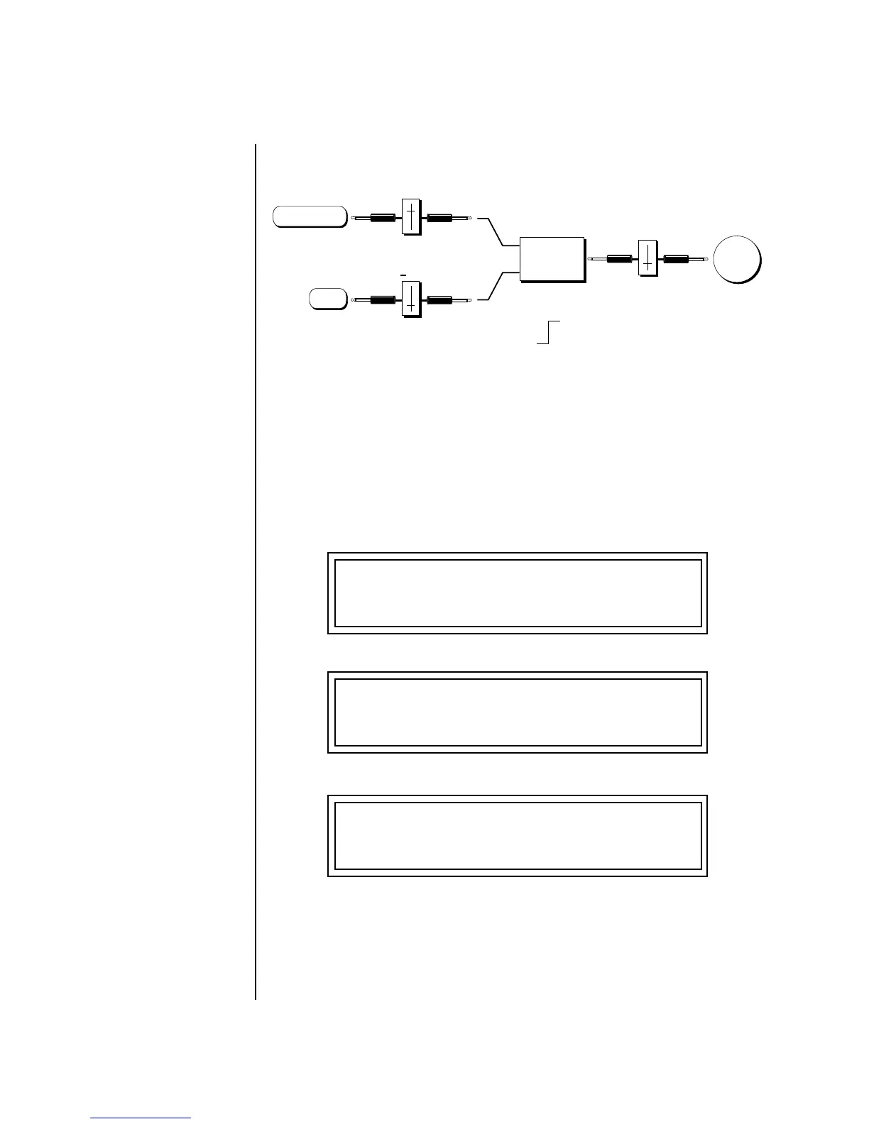
Preset Modulation Processors
But what if you want the velocity switch point to be something other than
64? Thanks to modulation processors, it can be done. Here's how.
Connect the DC level to the input of the switch along with the velocity
value. Note that more than one modulation source can be applied to the
input of a processor.
DC offset adds a fixed value based on the PatchCord Amount setting. If
applied to the switch along with the velocity, it changes the velocity value
required to trip the switch. By setting the DC amount to a negative
amount, higher velocity values are required to trip the switch. Setting the
DC value to a positive value would bring the velocity switch point down.
The PatchCord screens for this patch are shown below.
Switch
Velocity ~
Pitch
Cord
Cord
21
Cord
Switch On when
Velocity > 0
Switch value
is Scaled by
Cord Amount
DC
L1
PATCHCORD #01
Vel+- -> Switch +100
L1
PATCHCORD #02
DC -> Switch -021
L1
PATCHCORD #03
Switch -> Pitch +022
 Loading...