EasyIO FW Series – User Reference v3.0
28
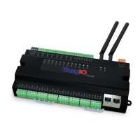
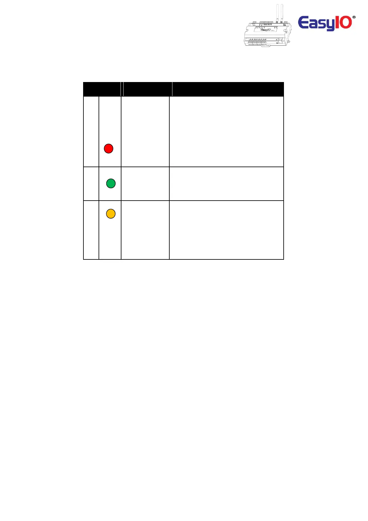
Button and LED indications. Image shown is an EasyIO FW-14.
Pattern: continuously blinking.
ERR is to indicate whenever there is
Communication errors between FM-02
module and base board.
Pattern: constantly light up.
The controller is undergoing firmware
upgrading. This is normal during firmware
upgrade process.
STS is used to indicate the heartbeat of the
Microcontroller. The STS LED will blink at
1-second interval in normal operation
TXRX is used to indicate when there are
Communication activities in Port 1.
(Transmitting or Receiving) on the
Communication port.
If BACnet MS/TP is enable both TX and RX
led blinking shows communication is
established successfully.
 Loading...