MF2E-E -B 2
- 8 -
SD card: support 32G SD memory card
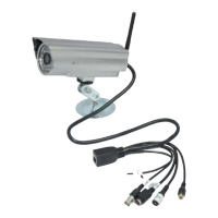
I/O interface: 1 channel alarm input, connect 3 and 4 interfaces ( ground,
trigger by low electric level ) ; TTL to control output, connect 1 and 2
interfaces ( 1 , 2 short connection ) .
4.
4.
4.
4. NETWORK
NETWORK
NETWORK
NETWORK CONNECTION
CONNECTION
CONNECTION
CONNECTION
P
P
P
P icture
icture
icture
icture 3-
3-
3-
3- network
network
network
network connection
connection
connection
connection scheme
scheme
scheme
scheme
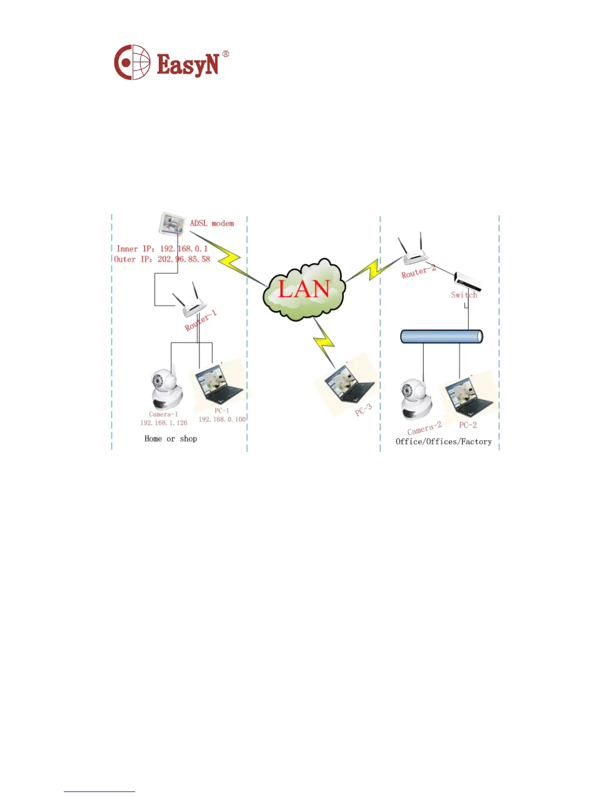
4.1 . CONNECTION INSTRUCTION
Before access IP Camera, first to confirm the network connection and the
power supply, to check if the status lens normal. For connection as picture
3:
1 ) camera-1 and camera-2 is connected to two different LANs
2 ) the two LANs must connect to internet and have routers connecting
through ADSL or optical fiber, etc.
3 ) computer-3 should be a device connecting to internet
4.2 . ACCESS INSTRUCTION
F or accessing camera, in addition to communication links remain open, it
also requires a simple settings for camera and network:
1 ) computer and camera are in the same LAN
F or access IP Camera via LAN, it should be confirmed that the computer
and camera in the same subnet, if they are not, then need to configure