4
WIRING AND DIP SWITCHES
All wiring to the DPM is done via rear terminal, de-pluggable connectors. Up to five
headers accept the wired connectors on the DPM. All units have at least two head-
ers, power input and signal input. Any combination of three additional circuit boards
with headers may be installed. These option boards are relay output, RS 485 serial
communications, and analog retransmission. The option boards occupy specific
locations in the DPM and are not interchangeable. All boards are keyed to prevent
installation in the wrong location.
Disconnect all power before wiring terminals. A safety hazard exists if
this precaution is not observed. Treat all control and count inputs as haz-
ardous since they may carry line voltage.
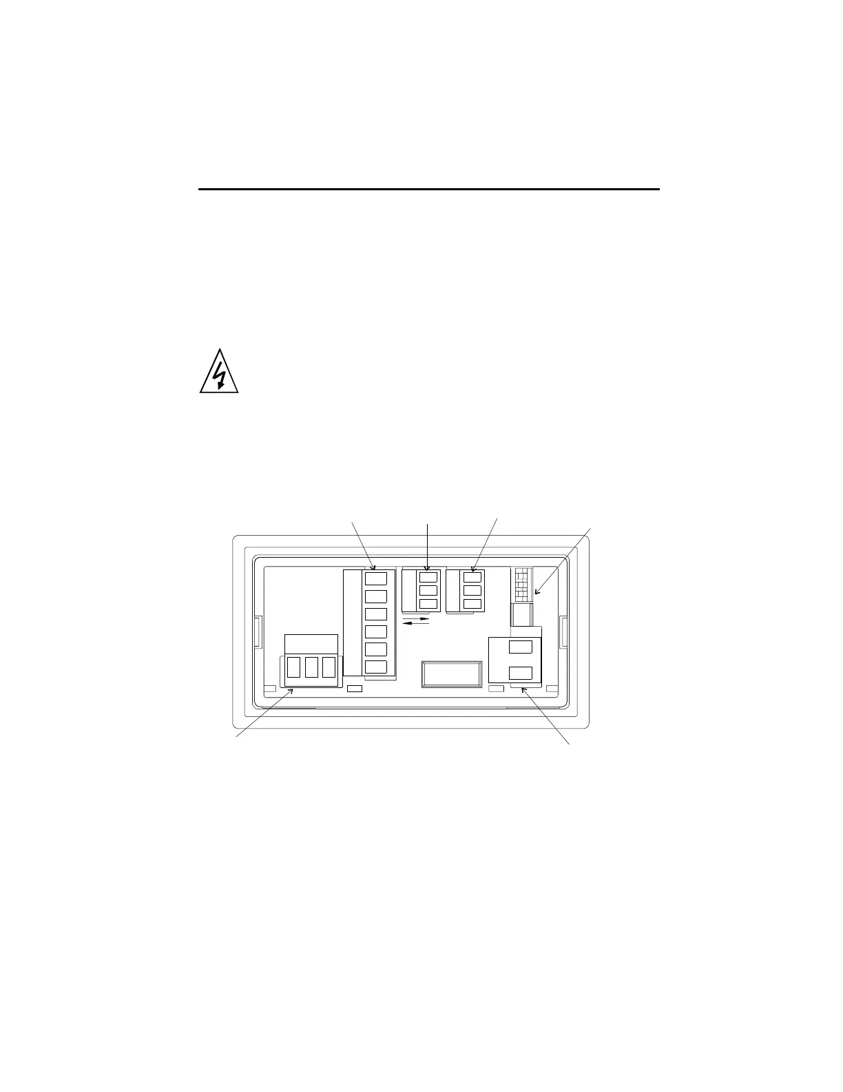
Rear Terminal Layout
Relay
Output
Connector
RS485
Communications
Connector
Analog
Output
Connector
DIP Switch
3 Position for 5A AC
and Process DPM
6 Position for AC/DC
Voltage and Current
Signal Input
2 Terminals for AC/DC
Voltage and Current
and 5A AC
4 Terminals for Process DPM
Power Input
2 Terminals for DC
Powered Units
3 Terminals for
AC Powered Units
Durant
®
1
1
1
1
11
Terminal Connector Ratings:
AC or DC Power Input / Relay Output / Signal: 10A, 250VAC;
Wire size: 12-24AWG (3.1mm
2
- 0.24mm
2
), 600V.
RS485 / Analog Output / Signal: 8A, 125VAC;
Wire size: 16-28AWG (1.3mm
2
- 0.1mm
2
), 300V.
WIRING
 Loading...