EFX48-xx Series with RM3-340/440 Installation and Operation Guide
62
Copyright © 2019 Eaton Corporation. All Rights Reserved.
IPN March 2019
Step 1 - Connect battery cables
Always check that the battery cables have been terminated to the correct system polarity
BEFORE connecting the batteries or enabling the battery e-Fuse based protection.
• Connecting batteries to the system with incorrect system polarity will void all warranty
claims.
1 Select battery cable to suit the maximum battery current and voltage drop
requirements.
2 Route the battery cables to the EFX48 unit within the RM3-340/440 system.
Take care when routing the cables to prevent the display and controls of
the EFX48 being obscured, as well as avoiding blocking the rectifier fan
vents. It may help to tie the cables onto features of the system rack, and tie
the cables together.
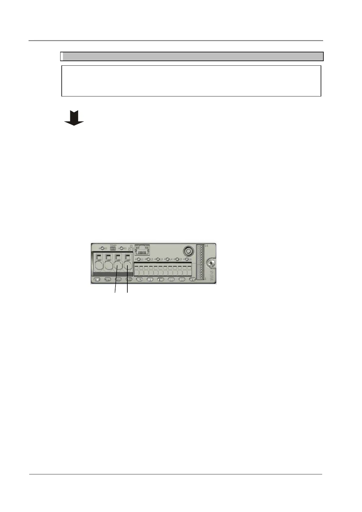
3 Strip the insulation and fit the common cables into battery connection terminal
marked “+”.
4 Strip the insulation and fit the live cables into the negative battery connection
terminals marked “B1” or “B2” (as appropriate for the battery being
terminated).
5
Ensure for each battery connection that matched ”+” and “–“ (B1 or B2)
terminals are used and cables are not crossed over different battery connections
.
Battery positive (+) common connection
i.e. B2 common
Battery negative (-) live connection i.e.
B2 live
 Loading...


