7
General Information
1.4 Emission Information Continued...
For generators 14kW and greater, the Emission Control System
code is EM (Engine Modification) and consists of the following
components:
• Air Induction System
~ Intake Pipe / Manifold
~ Air Cleaner
• Fuel Metering System
~ Carburetor / Mixer Assembly
~ Fuel Regulator
• Ignition System
~ Spark Plug
~ Ignition Module
• Exhaust System
~ Exhaust Manifold
~ Muffler
1.7 READY TO RUN
The "Ready to Run" on the display is ready when all of the following
conditions are true:
1. The AUTO/OFF/MANUAL switch is set to the AUTO position.
2. The utility voltage being supplied to the unit is being sensed
by the PCB. If the utility sense voltage is not connected to the
unit or if it is below approximately 150-160 volts AC, then
the system will display the message "No Utility Present". This
indicates that if the AUTO/OFF/MANUAL switch is placed in
the Auto position, the generator will start.
3. No alarms are present, for example, low oil pressure, high
temperature, etc.
1.8 FUEL REQUIREMENTS AND
RECOMMENDATIONS
With LP gas, use only the vapor withdrawal system. This type of
system uses the vapors formed above the liquid fuel in the storage
tank.
The engine has been fitted with a fuel carburetion system that
meets the specifications of the 1997 California Air Resources
Board for tamper-proof dual fuel systems. The unit will run on
natural gas or LP gas, but it has been factory set to run on natural
gas. Should the primary fuel need to be changed to LP gas, the
fuel system needs to be reconfigured. See the reconfiguring the
Fuel System section for instructions on reconfiguration of the fuel
system.
Recommended fuels should have a Btu content of at least 1,000
Btus per cubic foot for natural gas; or at least 2,520 Btus per
cubic foot for LP gas. Ask the fuel supplier for the Btu content of
the fuel.
Required fuel pressure for natural gas is five (5) inches to seven
(7) inches water column (0.18 to 0.25 psi); and for liquid pro-
pane, 10 inches to 12 inches of water column (0.36 to 0.43 psi).
The primary regulator for the propane supply is NOT INCLUDED
with the generator.
NOTE:
All pipe sizing, construction and layout must comply with NFPA
54 for natural gas applications and NFPA 58 for liquid propane
applications. Once the generator is installed, verify that the fuel
pressure NEVER drops below five (5) inches water column for
natural gas or 10 inches water column for liquid propane.
Prior to installation of the generator, the installer should consult
local fuel suppliers or the fire marshal to check codes and regula-
tions for proper installation. Local codes will mandate correct rout-
ing of gaseous fuel line piping around gardens, shrubs and other
landscaping to prevent any damage.
Special considerations should be given when installing the unit
where local conditions include flooding, tornados, hurricanes,
earthquakes and unstable ground for the flexibility and strength of
piping and their connections.
Use an approved pipe sealant or joint compound on all threaded
fitting.
All installed gaseous fuel piping must be purged and leak tested
prior to initial start-up in accordance with local codes, standards
and regulations.
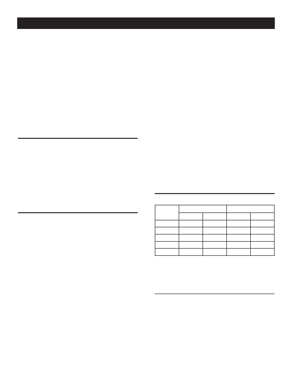
1.9 FUEL CONSUMPTION
Unit
Nat. Gas LP Vapor
1/2 Load Full Load 1/2 Load Full Load
7/8 kW 77 140 0.94/34 1.68/62
9/10 kW 102 156 1.25/46 1.93/70
13/14 kW 156 220 1.56/58 2.30/84
16/17 kW 183 261 1.61/59 2.57/94
18/20 kW 206 294 1.89/69 2.90/106
* Natural gas is in cubic feet per hour.
** LP is in gallons per hour/cubic feet per hour.
*** Values given are approximate.
Verify that gas meter is capable of providing enough fuel flow to
include household appliances.
1.9.1 BTU FLOW REQUIREMENTS - NATURAL GAS
Btu flow required for each unit based on 1000 Btu per cubic foot.
• 7kW — 140,000 Btu/Hour
• 9kW — 156,000 Btu/Hour
• 13kW — 220,000 Btu/Hour
• 16kW — 261,000 Btu/Hour
• 18kW — 294,000 Btu/Hour