04/10 MN04020001Z-EN
Parameter menu (PAR)
79
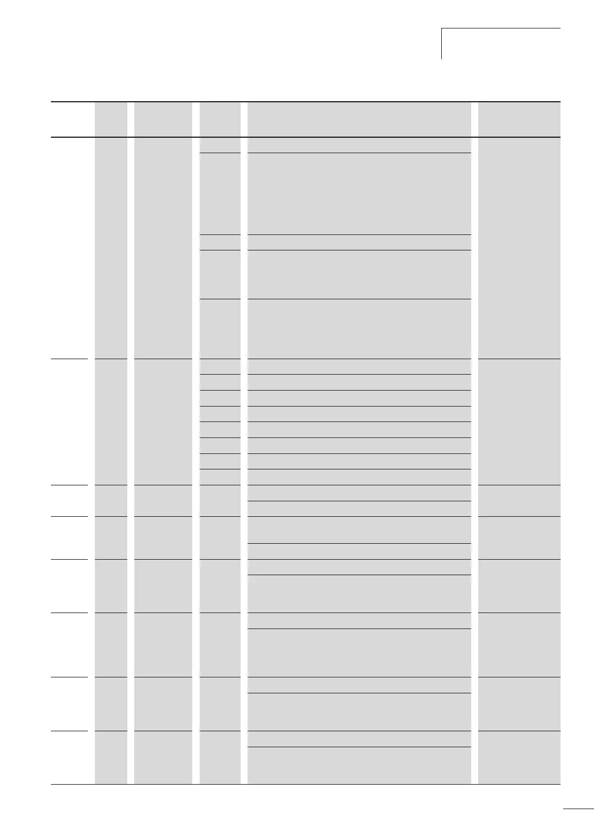
PNU ID Access right
RUN
Value Description Factory setting
(P1.3)
P3.1 300 / Start/Stop-Logic (rising edge). 3
0 DI1 (FWD), DI2 (REV), REAF.
REAF (Restart after Fault) = Restart after an error message
Function same as P3.1 = 3.
The automatic restart after an error message (FAULT) requires
setting P6.13 = 1.
The rising edge of the control voltage at control signal terminal
8 (DI1) or control signal terminal 9 (DI2) is then not controlled.
1 DI1 (FWD) + DI2 = REV (see example A, page 76).
2 DI1 (Start pulse), DI2 (Stop pulse).
Start and stop command via the control signal terminals 8
(DI1 = Start) and 9 (DI2 = Stop) by a momentary pulse (+24 V).
(see example B, page 76)
3 DI1 (FWD), DI2 (REV)
DI1 (control signal terminal 8) starts the drive with a clockwise
rotating field (FWD) and DI2 (control signal terminal 9) with an
anticlockwise rotating field (REV). Both control commands are
interlocked (exclusive OR).
P3.2 403 / Start signal 1 (FWD) 1
0 Deactivated
1 Activated via control signal terminal 8 (DI1).
2 Activated via control signal terminal 9 (DI2).
3 Activated via control signal terminal 10 (DI3).
4 Activated via control signal terminal 14 (DI4).
5 Activated via control signal terminal 15 (DI5).
6 Activated via control signal terminal 16 (DI6).
P3.3 404 / Start signal 2 (REV). 2
Allocation of the function to control signal terminals same as P3.2.
P3.4 412 / Reverse
(changes the direction of the field of rotation from FWD to REV.)
0
Allocation of the function to control signal terminals same as P3.2.
P3.5 405 / Ext. fault close 0
Allocation of the function to control signal terminals same as P3.2
Error message when applying +24 V to the assigned control signal
terminal (DI1 to DI6).
P3.6 406 / Ext. fault open 0
Allocation of the function to control signal terminals same as P3.2
Error message when switching off or interrupting
(wire-breakage-safe) the applied control voltage (+24 V) from the
assigned control signal terminal (DI1 to DI6).
P3.7 414 / Fault reset 5
Allocation of the function to control signal terminals same as P3.2.
Acknowledges a displayed error message (Reset) when switching
on +24 V on the assigned control signal terminal (DI1 to DI6).
P3.8 407 / Run Enable 0
Allocation of the function to control signal terminals same as P3.2.
Rotational direction-independent start release when switching on
+24 V on the assigned control signal terminal (DI1 to DI6).
 Loading...


