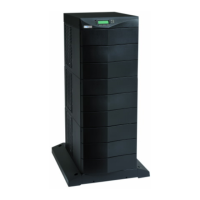
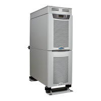
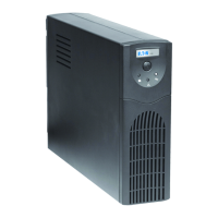
EATON Powerware
®
9170
+
UPS (3–18 kVA) User’s Guide S 164201393 Rev C www.powerware.com
i
Table of Contents
1 Introduction 1........................................................
Safety Warnings 2.....................................................................
Physical Features 5....................................................................
2 Installation Setup 9...................................................
Equipment Clearances 9.................................................................
Location Requirements 10................................................................
UPS Setup 10.........................................................................
Three- and Six-Slot Cabinets 10..........................................................
Nine- and Twelve-Slot Cabinets 11.......................................................
Caster Cart Installation (Three- and Six-Slot Cabinets) 12..........................................
Stabilizer Bracket Installation (Twelve-Slot Cabinet Only) 13........................................
Rack-Mount Installation (Three- and Six-Slot Cabinets) 14..........................................
Floor Anchor Kit Installation 16.............................................................
Moving the Cabinets 17..................................................................
3 UPS with Bypass Electrical Installation 19..................................
Input Current Ratings 21..................................................................
Bypass Switches 22.....................................................................
UPS Installation with an External Bypass Switch 25..............................................
System Wiring Diagrams 33...............................................................
4 UPS Electrical Installation 39............................................
Input Current Ratings 40..................................................................
UPS Electrical Installation 42..............................................................
System Wiring Diagrams 48...............................................................
5 Isolated Output Wiring Diagrams 53.......................................
Neutral-to-Ground Bonding for Isolated Output 54...............................................
System Wiring Diagrams 56...............................................................
6 Battery Cabinet Installation 61............................................
7 UPS Startup 67........................................................
Power and Battery Module Installation 68.....................................................
Startup for Plug-Receptacle Units 69.........................................................
 Loading...


