7 Accessories
7.1 Device-specific accessories
182 DC1…20… and DC1…OE1 Variable Frequency Drives 02/20 MN040059EN www.eaton.com
7.1.1 DXC-EXT-IO… coupling module
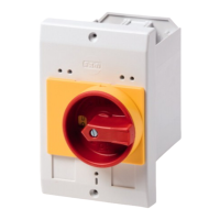
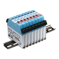
Coupling modules DXC-EXT-IO110 and DXC-EXT-IO230 can be used to
integrate the digital inputs on DC1 variable frequency drives directly into
circuits with 110 VAC / 230 VAC. In the actual coupling mode, the inputs
(connection terminals 1 to 4 and 12 and 13) are galvanically isolated from the
variable frequency drive’s digital inputs (DI1 to DI4).
Figure 90: DXC-EXT-IO110 and DXC-EXT-IO230
Figure 91: Block diagram DXC-EXT-IO110 and DXC-EXT-IO230
Parameters:
→
For more information on the coupling modules and on output
expansions, please refer to Application Note AP040032
(DC1, I/O Configuration).
P-12 = 0 Terminal mode (WE)
P-15 = 5 WE = The analog value on terminal 6 will be used as the
frequency reference value
(AI)
P-15 = 2 Terminal 12 and 13 digital input active (DI4)
P-18 = 0 RUN (WE)
2
DI1
3
DI2
4
DI3
1
5
+10 V
< 20 mA
6 7
0 V
0 V
8 9 10 11
12 13
1DC1 2 3 4 5 6 8 9 10 11
P-18 = 1
RUN
P-12 = 0
AI : P-15 = 5
DI4 : P-15 = 2
7
AI
0 ... +10 V
A0
0 ... +10 V/20 mA
N
DI4
N
f-Soll
f-Out
K1
250 V AC
220 V DC
1 A
4.7 kΩ
+
L
N

 Loading...
