Installing and Maintaining i-on10
Page 14
Detector (zone) wiring types
Before installation, you need to choose the wiring type (method) to use for any wired
detectors: Fully-Supervised Loop (FSL), 4-wire Closed Circuit (CC), or 2-wire CC, as
described below. You must use the same wiring type for all wired detectors.
You will need to ensure that all detectors are wired correctly and that you select the default
wiring type during the initial power-up procedure.
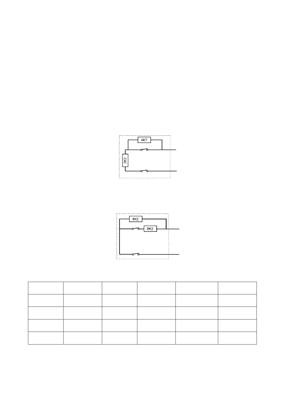
Fully Supervised Loop (FSL)
This uses a single pair of wires for each detector, with resistors at the end of the line and
across the alarm contact (Figure 2). The resistors allow the system to monitor for short-
circuit or open-circuit conditions to guard against cable tampering.
The End-of-Line (EOL) and alarm contact resistors can be any of the following values
(respectively): 2k2 and 4k7, 1k and 1k, 2k2 and 2k2, or 4k7 and 4k7. The resistance bands
for FSL are as shown in Table 4.
Figure
FSL connections for 2k2/4k7, 1k/1k, 2k2/2k2 and 4k7/4k7
FSL with 8k2/8k2 resistors (for use with Guardall
®
resistors)
Figure 3 shows the wiring method when using 8k2 and 8k2 resistors.
Figure
FSL connections for 8k2/8k2
Table 4: FSL Resistor Bands
Double Doors
If required, two door contacts can be connected to the same zone using the resistor
configuration shown in Figure 4. In this configuration, the zone must have the Double

 Loading...