(21)
4.3.2 Control Signal Wiring
Connect wires to the control connector for remote operation and remote monitoring.
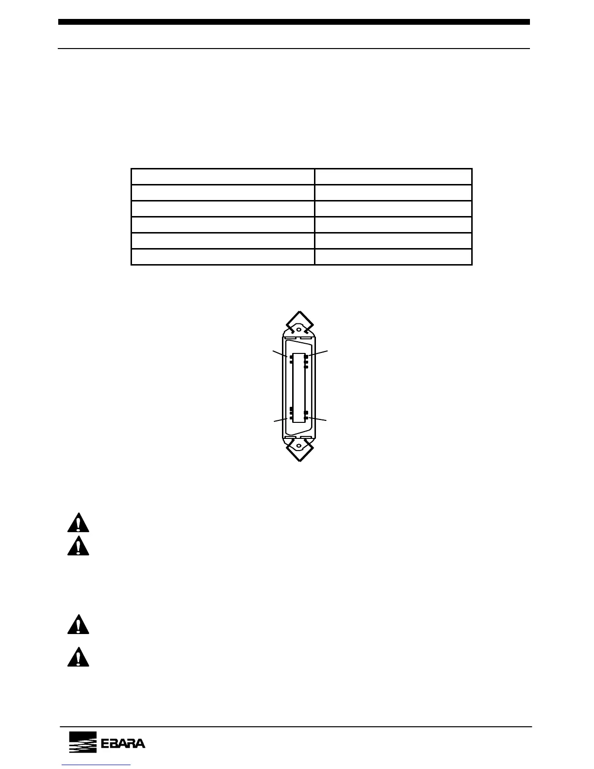
Tables 4.4 and 4.5 and Figures 4.5 and 4.6 show the pin assignments.
Table 4.4 Receptacle Specifications
(Identical for all types)
Receptacle type 57FE-40500
Receptacle manufacturer DDK. Ltd.
Adapted plug type 57-30500
Suitable wire size AWG #24
Applied voltage for input *1 12V DC 20 mA
Contact capacity of output *2 50V DC/Maximum. 50 mA
*1. Apply voltage through pump.
*2. Apply voltage through equipment.
1
26
5025
Figure 4.5 Control Signal Receptacle
(As seen from connecting side)
CAUTION
Do not wire vacant pins.
CAUTION
Apply 12V DC power for input signals on the pump side. Do
not apply this voltage on the equipment side.
The output signals are generated from an open collector
output. Apply a voltage not exceeding 50V DC on the
equipment side.
CAUTION
Wire all signals with the correct polarity
(SIGNAL/COMMON).
CAUTION
When output signals energize an inductive load, such as a
relay, insert a diode (100V. 1A class) to absorb the back
electromotive force from surge currents.
EBARA Corporation