55
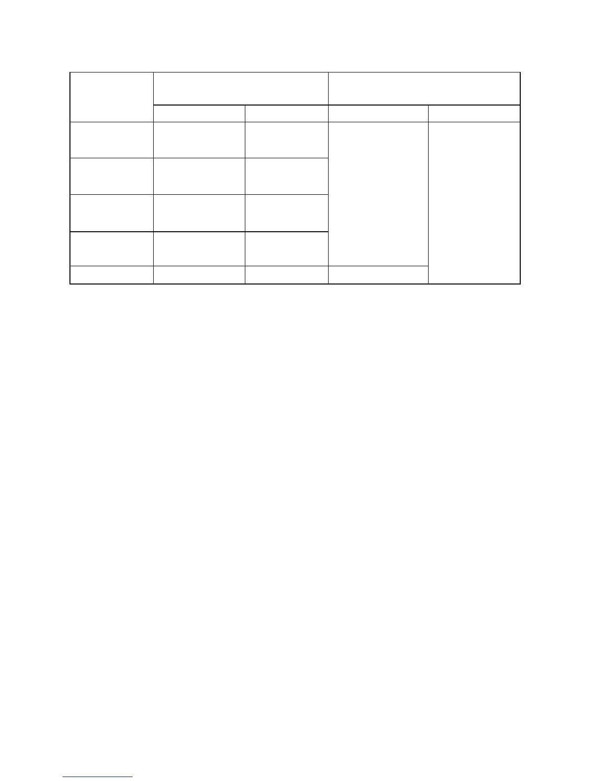
Table 1 Input Impedance
Lead Electrode
The summit vlaue of deflectionfront
traced by K open circuit (mm)
Lead Position
Connecting to P1 Connecting to P2 Single Channel ECG Multi-channel ECG
Ⅰ,Ⅱ,aVR, aVL,
aVF,V1
R
All other Lead
electrodes
Ⅰ,Ⅲ,aVL, aVR,
aVF,V2
L
All other Lead
electrodes
Ⅱ,Ⅲ,aVF, aVR,
aVL,V3
F
All other Lead
electrodes
Vi(i is 1~6)
Ci
All other Lead
electrodes
8
Vx, Vy, Vz A,C,F,M I, E, H —
8
1.13 Features of Amplitude Frequency
When the filter is shut off, take 10Hz sine wave as reference.
From 0.5 to 50Hz, the tolerance of amplitude of frequency is -10%~+5%.
From 50 to 70Hz, the tolerance of amplitude of frequency is -30%~+5%
1.14 Features of Low Frequency .Time Constant no less than 3.2s
1.15 Baseline stability
1.15.1 Stable Power: baseline drifting should be no more than 1mm
1.15.2 Unstable Power: baseline drifting should be no more than 1mm
1.15.3 Sensitivity (no signal input) : baseline drifting should be no more than 2mm
1.15.4 Temperature Drift: From 5~40℃, baseline drifting should be no more than 0.5mm/℃
1.16 Paper Speed
6.25 mm/s 12.5 mm/s 25mm/s and 50mm/s , tolerance : ±5%
1.17 The impact of AC to DC conversion
The DC indicator should be lit when changing AC to DC conversion. All operation
should be normal.
1.18 Printing resolution (Thermal matrix printing)
Y axis ≥8 dots/mm;
X axis ≥32 dots/mm(Paper speed 25 mm/s)、≥16 dots/mm(Paper speed 50 mm/s).
1.19 Request of Thermal matrix printing
Printer can record letters and marks. When recording, the printer could print out lead, paper
speed, gain and etc.