CHAIN BRAKE SYSTEM
CS-310
44
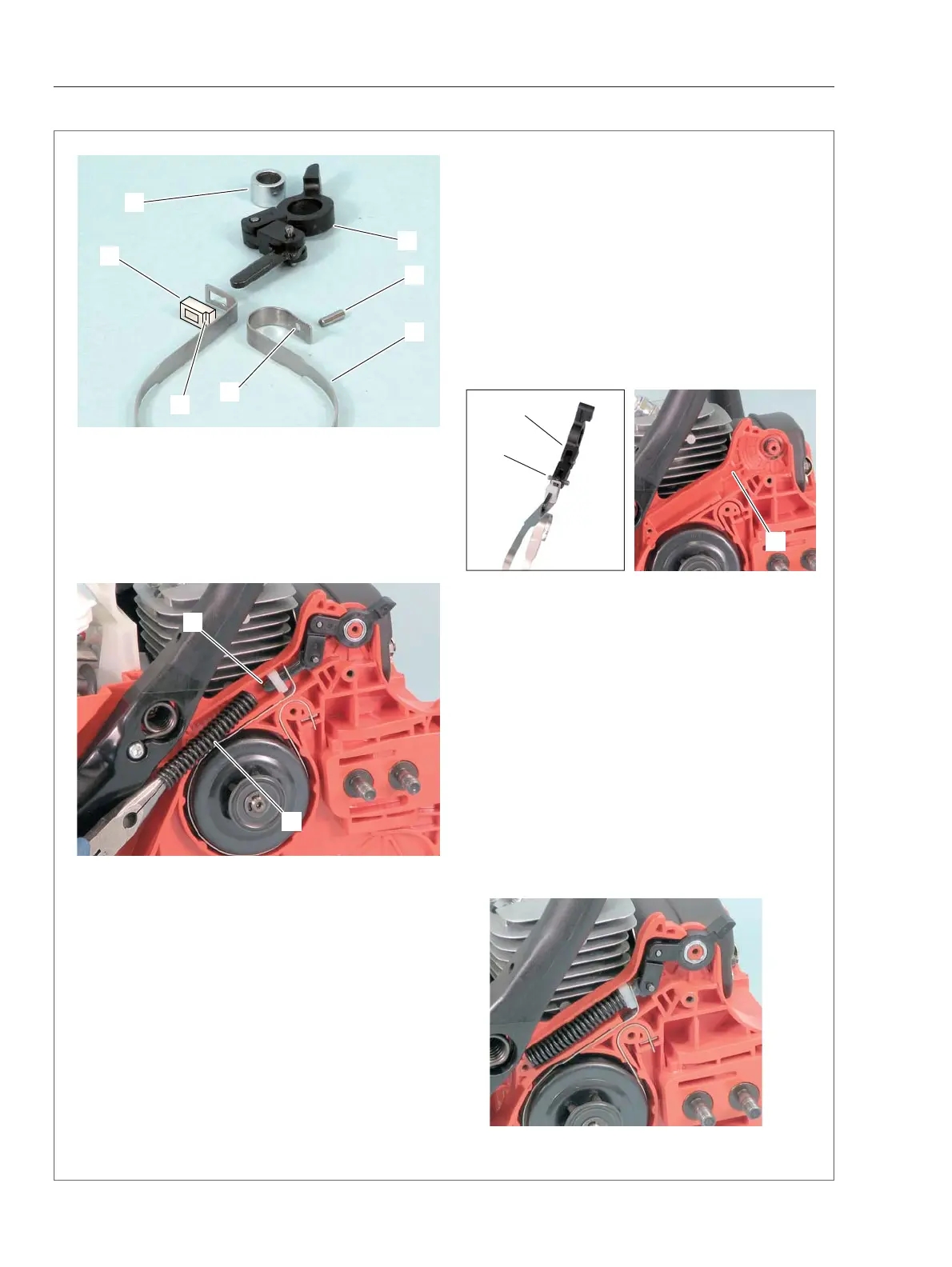
6-2 Assembling brake parts
1. Set brake band (A) together with spacer (B),
brake connector (C) and spacer (D), placing the
notch (b) of spacer (B) as shown. Install roller (E)
through brake band hole (a).
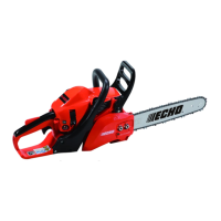
2. Install brake band and other parts (refer to the
above 1.) on engine cover as shown in the left pic-
ture. Make sure the pin (c1) of brake connector (C)
is engaging with the groove (F) of engine cover.
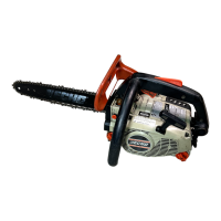
3. Slide in compression spring (G) to the end (c2)
of brake connector as sown.
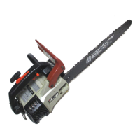
4. Push compression spring (G) with longnose pli-
ers etc. and install compression spring in engine
cover as shown in the below picture.
5. Apply molybdenum grease on entire compres-
sion spring and other friction parts.
6. Reinstall brake cover and other parts.
A
a
E
C
D
B
b
G
c2
c1
C
F