17
Installing the Motherboard
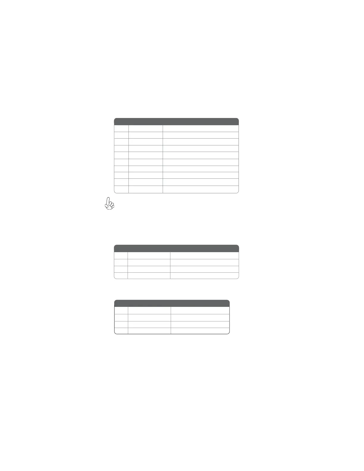
F_USB1~2: Front Panel USB headers
The motherboard has four USB ports installed on the rear edge I/O port array.
Additionally, some computer cases have USB ports at the front of the case. If you
have this kind of case, use auxiliary USB connector to connect the front-mounted
ports to the motherboard.
Please make sure that the USB cable has the same pin assignment as
indicated above. A different pin assignment may cause damage or system
hang-up.
1 USBPWR Front Panel USB Power
2 USBPWR Front Panel USB Power
3 USB_FP_P0- USB Port 0 Negative Signal
4 USB_FP_P1- USB Port 1 Negative Signal
5 USB_FP_P0+ USB Port 0 Positive Signal
6 USB_FP_P1+ USB Port 1 Positive Signal
7 GND Ground
8 GND Ground
9 Key No pin
10 NC Not connected
Function
Pin Signal Name
SPDIFO: SPDIF out header
This is an optional header that provides an S/PDIF (Sony/Philips Digital Interface)
output to digital multimedia device through optical fiber or coaxial connector.
1 SPDIF SPDIF digital output
2 +5VA 5V analog Power
3 Key No pin
4 GND Ground
Pin Signal Name Function
CD_IN: CD Audio In connector
4 CD_R CD Audio in right channel
Pin Signal Name Function
1 CD_L CD Audio in left channel
2 GND Ground
3 GND Ground
Function
Pin Signal Name
 Loading...