Chapter 1
| Switch Description
Overview
– 10 –
Key Hardware
Components
The switches consist of several key hardware components. This manual describes
each specific component, or related components, together with their installation
requirements and procedures in each chapter. To understand each component in
detail, refer to the relevant section.
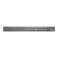
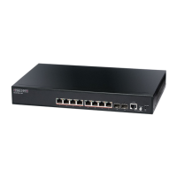
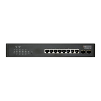
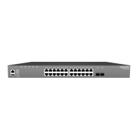
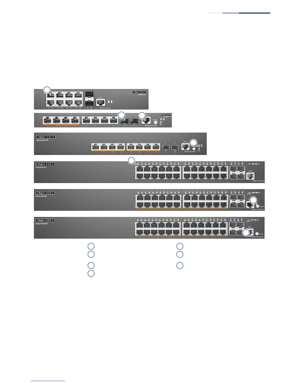
Figure 1: Switch Front Panels
10/100/1000BASE-T RJ-45 Ports
The switch contains 24 10/100/1000BASE-T RJ-45 ports that support 10/100/
1000BASE-T copper links to other devices. For more information, see “How to
Connect to Twisted-Pair Copper Ports” on page 36.
Port Status LEDs
For information on port status LED indicators, see “Understanding the Port Status
LEDs” on page 34.
10/100/1000BASE-T RJ-45 Ports 10/100/1000BASE-T RJ-45 Port LED
Combination Gigabit RJ-45/SFP Ports PoE button (ECS2100-10P/ECS2100-10PE/
ECS2100-28P/ECS2100-28PP)
RJ-45 Console Port Reset / Factory Default button
System LEDs (Power/PoE Max/Diag)

 Loading...