Chapter 4
| Power and Grounding
Grounding the Chassis
– 29 –
Grounding the Chassis
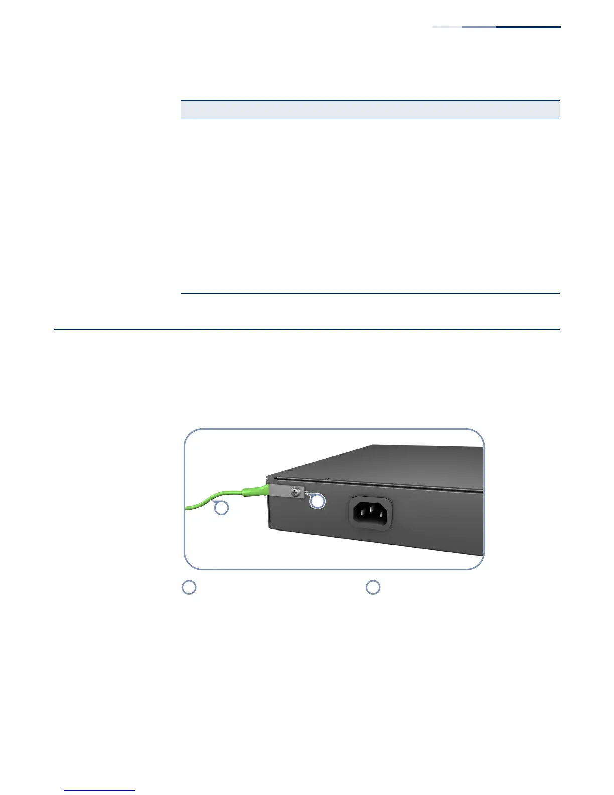
The rear panel of the switch chassis includes a single hole grounding terminal. It
must be connected to ground to ensure proper operation and to meet
electromagnetic interference (EMI) and safety requirements.
Figure 15: Grounding Terminal
Before powering on the switch, ground the switch to earth as described below.
1. Ensure that the rack in which the switch is to be mounted is properly grounded
and in compliance with ETSI ETS 300 253.
2. Ensure that there is a good electrical connection to the grounding point on the
rack (no paint or isolating surface treatment).
3. Disconnect all power cables to the switch.
Table 2: AC Power Supply Specifications
Item Description
AC Input ECS2100-10T: AC 100-240 V, 50-60 Hz, 0.5 A
ECS2100-10P: AC 100-240 V, 50-60 Hz, 2.1 A
ECS2100-28T: AC 100-240 V, 50-60 Hz, 0.5 A
ECS2100-28P: AC 100-240 V, 50-60 Hz, 3.2 A
ECS2100-28PP: AC 100-240 V, 50-60 Hz, 5.8 A
AC-DC Power Adapter
(ECS2100-10PE only)
Input: AC 100-240 V, 50-60 Hz, 1 A
Output: 54 VDC, 1.67A
Power Supply 100-240 VAC, 50-60 Hz, auto-sensing
Total Power Consumption ECS2100-10T: 8 W
ECS2100-10P: 160 W
ECS2100-10PE: 80 W
ECS2100-28T: 20 W
ECS2100-28P: 260 W
ECS2100-28PP: 490 W
ECS2100-28PP+ one external power supply: 950 W
Grounding Wire Grounding Terminal

 Loading...