Chapter 4
| Power and Grounding
How to Connect to AC Power
– 30 –
4. Attach a 6 AWG stranded copper wire to the grounding terminal on the switch.
The switch chassis is connected internally to 0 V. This circuit is connected to the
single-hole grounding terminal on the rear panel of the switch (left of the AC
power socket). The surface area around this terminal is not painted in order to
provide for a good connection.
5. Attach the grounding wire to the ground point on the rack.
Caution:
The earth connection must not be removed unless all supply
connections have been disconnected.
How to Connect to AC Power
Connect the switch to an AC power source to power on. Verify that the external AC
power requirements for the switch can be met as listed below:
ECS2100-10T: AC 100-240 V, 50-60 Hz, 0.5 A
ECS2100-10P: AC 100-240 V, 50-60 Hz, 2.1 A
ECS2100-28T: AC 100-240 V, 50-60 Hz, 0.5 A
ECS2100-28P: AC 100-240 V, 50-60 Hz, 3.2 A
ECS2100-28PP: AC 100-240 V, 50-60 Hz, 5.8 A
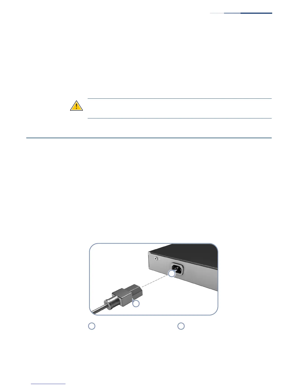
To connect the switch to a power source:
1. Plug the power cord into a grounded, 3-pin, AC power source.
Figure 16: AC Power Cord and Power Socket
2. Insert the plug on the other end of the power cord directly into the AC input
socket on the back of the switch.
AC Power Cord AC Power Socket

 Loading...