Chapter 1
| Switch Description
Overview
– 11 –
Mode Button
Pressing the Mode button on the front panel will change the Diag LED and the PoE-
enabled port LEDs to display PoE status. For more information, see “Understanding
the System Status LEDs” on page 42.
System LEDs
For information on system status LED indicators, see “Understanding the System
Status LEDs” on page 42.
Port LEDs
For information on port status LED indicators, see “Understanding the Port Status
LEDs” on page 31.
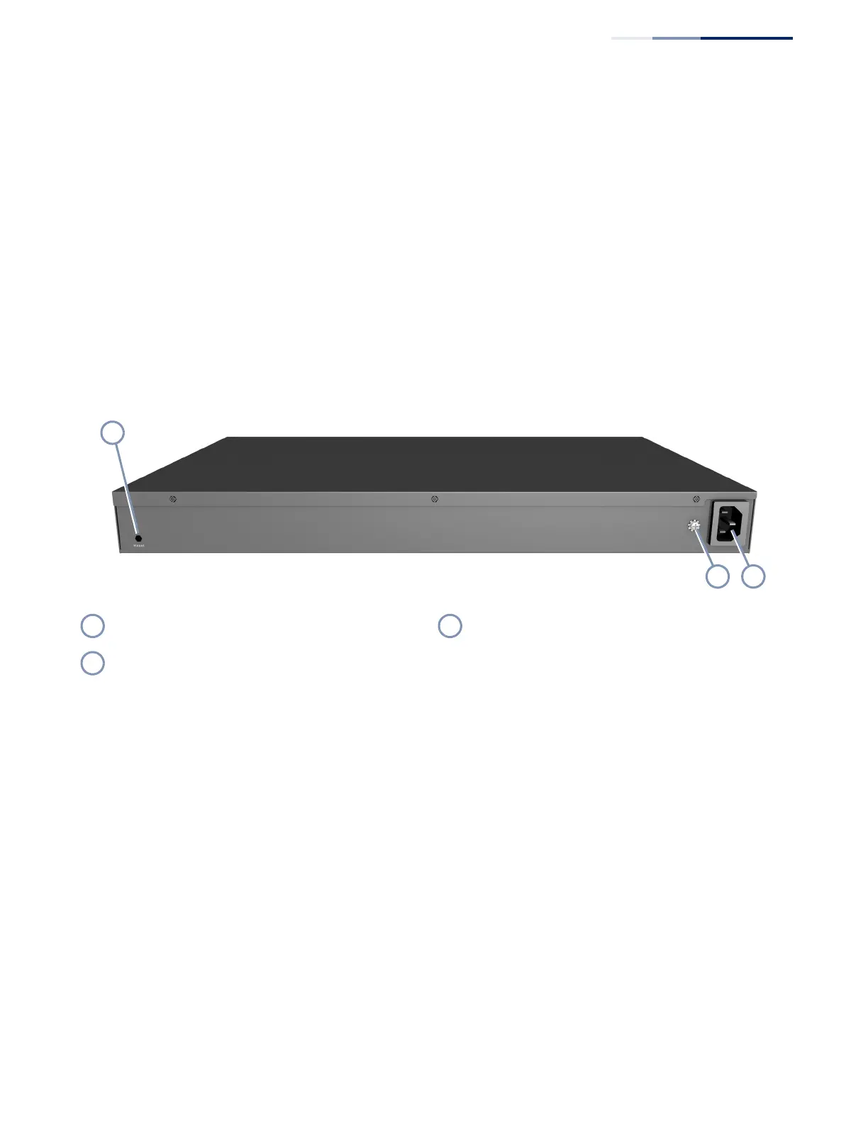
Figure 2: Rear Panel
Cooling Fans and Vents
The switch must be installed in a properly cooled and ventilated environment. For
more information. For more information, see “Switch Cooling Requirements” on
page 23.
AC Power Socket
The switch requires a 100-240 VAC, 50-60 Hz AC power source. For more
information on the switch power input, how to connect it, and how to power-on
the switch, see “How to Connect to AC Power” on page 27.
Grounding Terminal
The switch includes a grounding terminal that must be connected to a ground
source that provides local earth potential. For more information, see “Grounding
the Chassis” on page 26.
Reset Button AC Power Socket
Grounding Point
 Loading...