Chapter 6
| Switch Management
Understanding the System Status LEDs
– 42 –
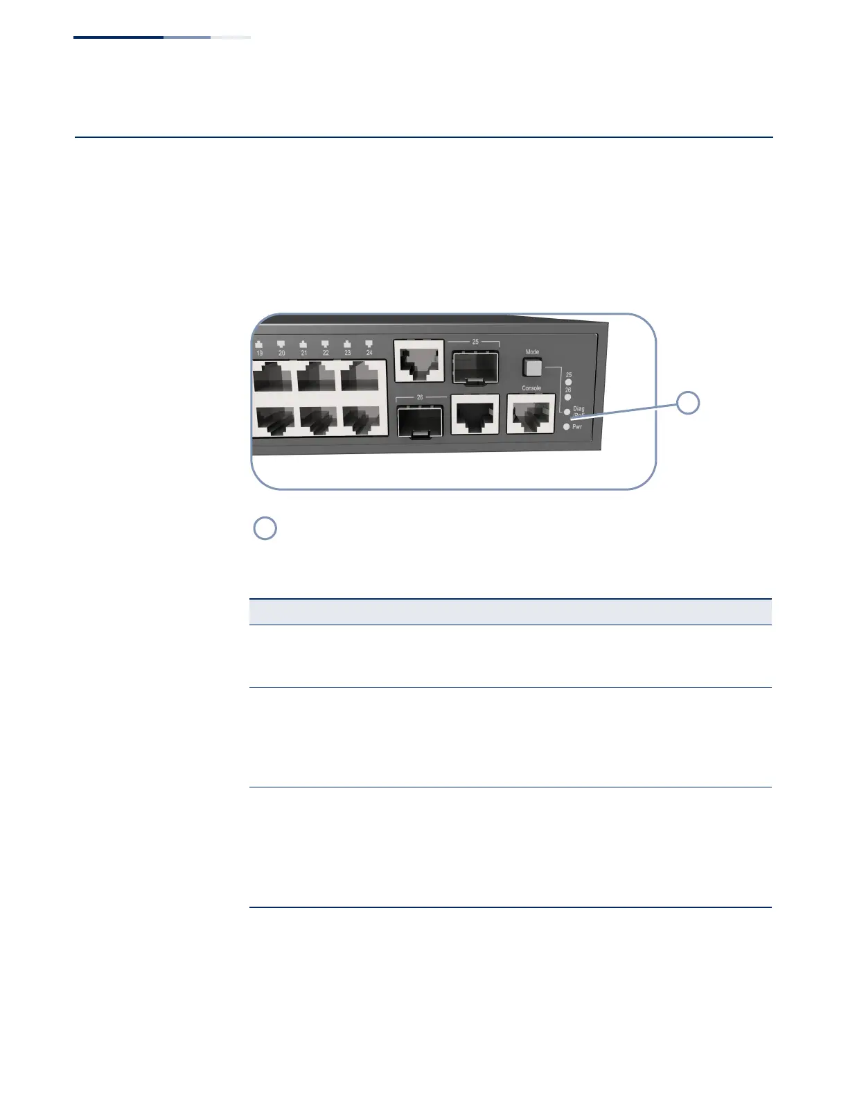
Understanding the System Status LEDs
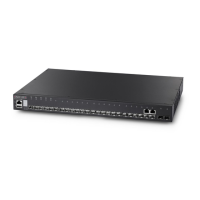
The switch includes a display panel of key system LED indicators. The LEDs, which
are located on the front panel, are shown below and described in the following
table.
Figure 20: System Status LEDs
(
System Status LEDs
Table 9: System Status LEDs
LED Condition Status
PWR On Green Internal power operating normally.
Off No AC power is connected or the internal power supply
has failed.
DIAG
(Diagnostic)
On Green The system diagnostic test has completed successfully.
On Amber System diagnostic in progress.
Blinking Amber The system self-diagnostic test has detected a fault.
Blinking Green The switch system is booting up.
PoE Status On Amber Port LEDs display the individual port’s PoE status.
Blinking Amber The PoE device power draw on the switch has reached at
least 95 percent of the maximum switch power output
capacity.
Off
Port LEDs display the individual port’s link and activity
status.
 Loading...