Chapter 1
| Switch Description
Overview
– 10 –
Key Hardware
Components
The switch consists of several key hardware components. This manual describes
each specific component, or related components, together with their installation
requirements and procedures in each chapter. To understand each component in
detail, refer to the relevant section.
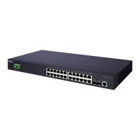
Figure 1: Front Panel ECS3510-26P
10/100BASE-T RJ-45 Ports
The switch contains 24 10/100BASE-T RJ-45 ports that support 10/100/1000BASE-T
copper links to other devices. For more information, see “How to Connect to
Twisted-Pair Copper Ports” on page 34.
Combination SFP/RJ-45 Ports
The switch contains two combo ports made up of two Small Form Factor Pluggable
( SFP) transceiver slots that are each logically connected with one of two 1000BASE-
T RJ-45 ports. At any one time, a “combo” port can only have one of the pair, the SFP
slot or the RJ-45 port, enabled. For more information on connecting the SFP ports,
see “How to Connect to SFP Fiber Optic Ports” on page 38.
Console Port
The RJ-45 connector on the front panel far right side that is labeled “Console”
provides an out-of-band serial connection to a terminal or a PC running terminal
emulation software. The port can be used for performing switch monitoring and
configuration. For more information, see “How to Connect to the Console Port” on
page 43.
10/100BASE-T Port LEDs System LEDs
10/100BASE-T RJ-45 Ports 1-24 Combo Port LEDs
Gigabit SFP Slot / 1000BASE-T RJ-45 Combo Port 25 Mode Button
RJ-45 Console Port Gigabit SFP Slot / 1000BASE-T RJ-45 Combo Port 26
 Loading...