Fiber Optic SFP Devices
4-3
4
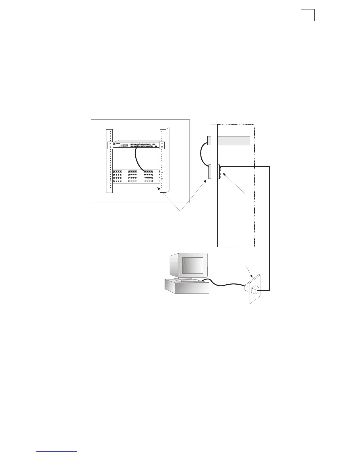
1. Attach one end of a patch cable to an available port on the switch, and the other
end to the patch panel.
2. If not already in place, attach one end of a cable segment to the back of the
patch panel where the punch-down block is located, and the other end to a
modular wall outlet.
3. Label the cables to simplify future troubleshooting. See “Cable Labeling and
Connection Records” on page 4-6.
Figure 4-2 Wiring Closet Connections
Fiber Optic SFP Devices
An optional Gigabit SFP transceiver (1000BASE-SX, 1000BASE-LX or
1000BASE-ZX) can be used for a backbone connection between switches, or for
connecting to a high-speed server.
Each single-mode fiber port requires 9/125 micron single-mode fiber optic cable with
an LC connector at both ends. Each multimode fiber optic port requires 50/125 or
62.5/125 micron multimode fiber optic cabling with an LC connector at both ends.
Equipment Rack
(side view)
Network Switch
Patch Panel
Punch-Down Block
Wall
 Loading...