© Edwards Limited 2008. All rights reserved. Page 3
Edwards and the Edwards logo are trademarks of Edwards Limited.
Introduction
S900-01-880 Issue C
MSeal booster pumps have a mechanical shaft seal on the drive shaft, and labyrinth shaft-seals between the gearbox
and the swept volume. Process isolation booster pumps have a mechanical shaft seal on the drive shaft, and
mechanical seals between the gearbox and the swept volume.
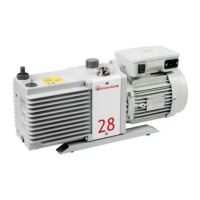
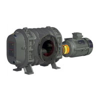
The booster pump general arrangements are shown in Figures 1 and 2.
1.4 General information
The booster pumps are available in horizontal (H) and vertical (V) configurations. The models of booster pumps are
the 607, 615 and 622 and these model numbers denote the pump body lengths: 7.0, 15.0 and 22.0 inches. The booster
pumps are available as bareshaft (belt driven) pumps, and as direct drive pumps (with shaft-mounted motors).
The booster pump gear centre distance is 6 inches. The booster pump have normal operation limits from 800 to 3600
r min-1 (r.p.m.). The volumetric pumping rates increase with body length and rotational speed. Pump components
in contact with the pumped gases are cast iron and carbon steel.
Refer to Table 1 to determine the operational limits for the booster pumps. The limits are based on compression and
pumping speeds for the specific application. Table 1 provides the maximum performance limits of the pumps. The
limits, backing pump speed and gas loads determine the cut-in pressure and continuous operation pressure limits.
Edwards can recommend cut-in and operation limits when supplied with chamber size, backing pump and gas load
information. The first limit reached during operation is the limiting factor. Control devices such as timers and
pressure and temperature switches may be required to properly control the operation of the booster pumps.
1.5 Booster pump models
The booster pumps are available in two versions:
H model booster pumps have vertical connections and are configured for horizontal gas flow through the
pump. (“H” appears in the Item Number of these pumps.)
V model booster pumps have horizontal connections and are configured for vertical gas flow through the
pump. (“V” appears in the Item Number of these pumps.)
The 615 booster pump is available with an optional bypass valve (see Section 1.9) which allows pump operation from
atmospheric pressure and reduces pump-down time. The booster pumps can be prepared hydrocarbon free for oxygen
service. Variable frequency (speed) drives are available for the pumps.
Table 1 - Application data
Pump model
607 615 615B* 622
Maximum pressure differential 5.06 x 10
4
Pa
506 mbar
380 Torr
5.06 x 10
4
Pa
506 mbar
380 Torr
Not applicable 3.33 x 10
4
Pa
333 mbar
250 Torr
Maximum temperature rise 135 ºC
275 ºF
135 ºC
275 ºF
135 ºC
275 ºF
121 ºC
250 ºF
Maximum discharge temperature 191 ºC
375 ºF
191 ºC
375 ºF
191 ºC
375 ºF
177 ºC
350 ºF
Maximum displacement † 2056 m
3
h
-1
1212 cfm
4412 m
3
h
-1
2600 cfm
4412 m
3
h
-1
2600 cfm
6528 m
3
h
-1
3840 cfm
Inlet and exhaust connection: ASA 6 inches 8 inches 8 inches 8 inches
Noise level average at ultimate vacuum * < 85 dB(A) < 85 dB(A) < 85 dB(A) < 85 dB(A)
* With bypass valve
† At 3600 r min
-1
(3600 rpm)
 Loading...