S900-01-880 Issue C
Page 6 © Edwards Limited 2008. All rights reserved.
Edwards and the Edwards logo are trademarks of Edwards Limited.
Introduction
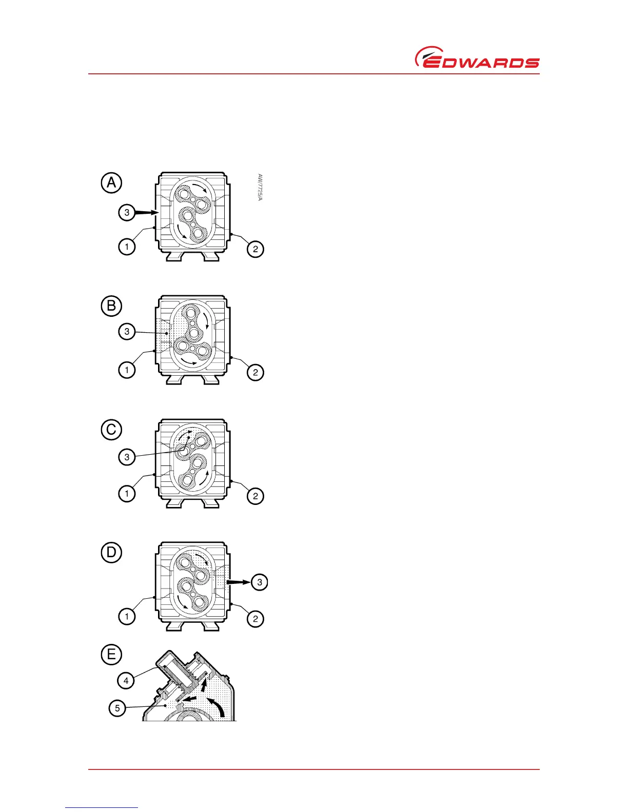
1.6 Principle of operation
The basic operation of an H (horizontal) booster is shown in Figure 3.
Figure 3 - Principle of operation
Detail A - Gas (3) enters the pump body through the inlet (1).
In the pump body, the upper impeller rotor rotates clockwise,
and the lower impeller rotor rotates anticlockwise
(counterclockwise).
Detail B - As the impeller rotors rotate, gas (3) is drawn into
the volume between the pump body wall and the rotors.
Detail C - As the rotors rotate further, gas (3) is trapped
between the pump body wall and the rotors, and is transferred
towards the outlet (2). The rotors rotate with precise timing to
maintain the proper clearances, limiting gas back flow.
Detail D - As the rotors rotate further, the gas (3) is discharged
through the pump outlet (2). The pump discharges four
volumes for every full rotation of the drive shaft.
Detail E: bypass valve operation (only applicable to pumps
with a bypass valve) - The optional integral bypass valve limits
the pressure differential across the pump. During pump
operation, if the compression creates an excessive pressure
differential across the pump, the bypass valve (4) opens, to
allow a portion of the compressed gases (5) to flow back
towards the inlet side of the pump.
 Loading...