S900-01-880 Issue C
Page 4 © Edwards Limited 2008. All rights reserved.
Edwards and the Edwards logo are trademarks of Edwards Limited.
Introduction
You must never operate the booster pump unless it is installed in a proper vacuum system with adequate guarding to
protect people from injury. You must fit safety guards to bareshaft booster pumps before operation.
Note that:
“B” in the pump Item Number specifies that the pump has a bypass valve.
“5H” or “5V” in the pump Item Number specifies that the pump is a process isolation booster pump,
otherwise the pump is an MSeal booster pump.
“HR” or “VR” at the end of the Item Number specifies that the pump is a standard service bareshaft pump
(with hydrocarbon oil), “HR101” or “VR101” at the end of the Item Number specifies that the pump is an
oxygen service (hydrocarbon free) bareshaft pump, otherwise the pump is a standard service pump (with
hydrocarbon oil).
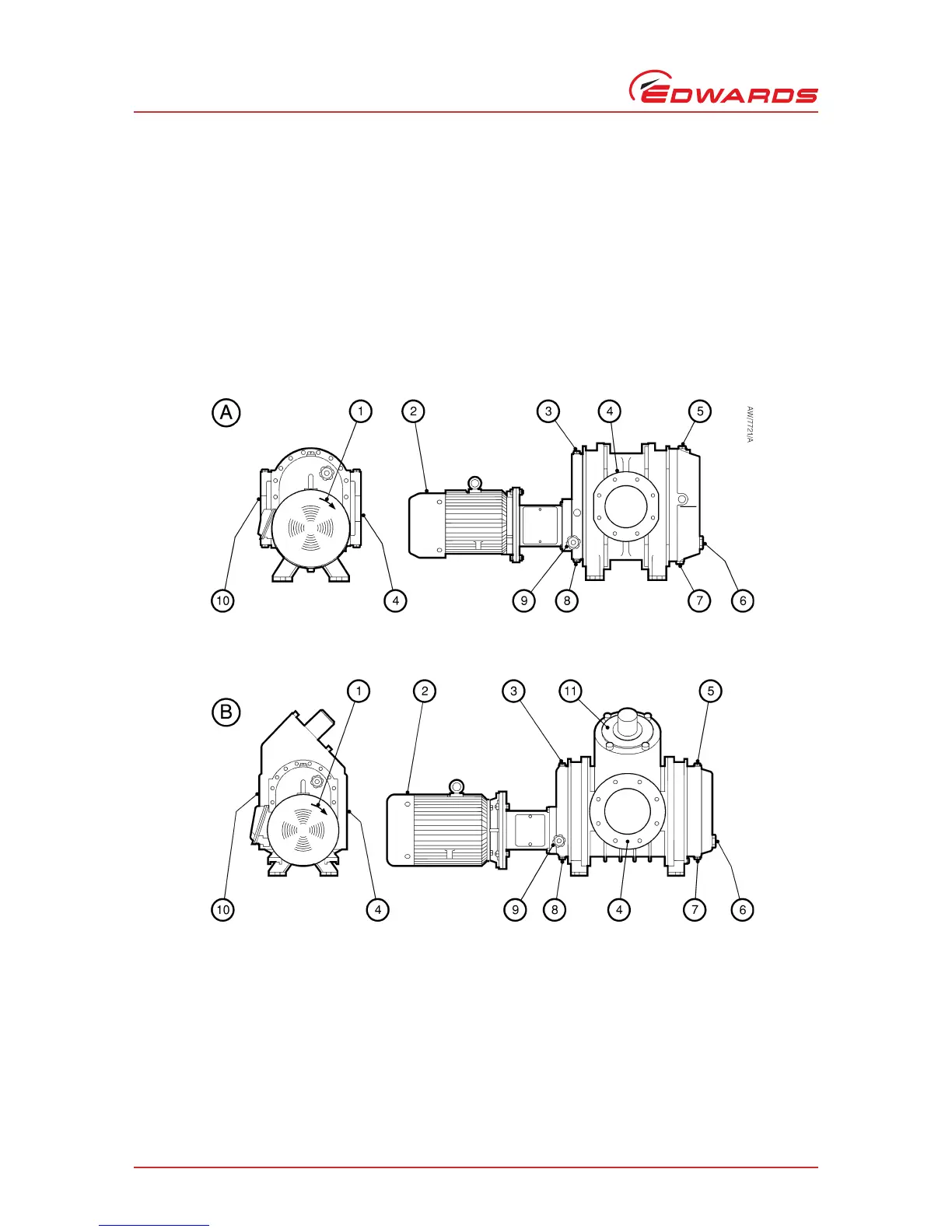
Figure 1 - General arrangement of the H (horizontal) booster
A. Standard direct drive pump
B. Direct drive pump with bypass valve
1. Direction of rotation arrow
2. Motor (IEC frame shown)
3. Oil filler plug (drive end)
4. Inlet
5. Oil filler plug (gear end)
6. Oil-level sight-glass (gear end)
7. Oil drain plug (gear end)
8. Oil drain plug (drive end)
9. Oil-level sight-glass (drive end)
10.Outlet
11.Bypass valve
 Loading...