A708-01-880 Issue E
Page 8 © Edwards Limited 2013. All rights reserved.
Edwards and the Edwards logo are trademarks of Edwards Limited.
Introduction
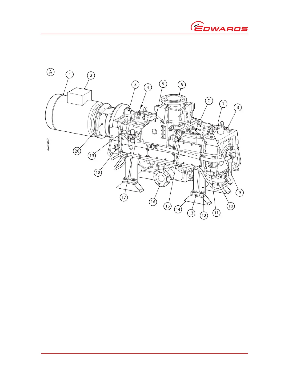
Figure 3 - The CDX pump (Sheet 1 of 2)
1. pump motor (typical)
2. Motor terminal box (typical)
3. Gearbox vent filter
4. Gearbox oil filler plug and bonded seal (in filler
port)
5. Heat exchanger
6. Pump inlet
7. End cover vent filter
8. End cover oil filler plug and bonded seal (in filler
port)
9. Temperature transmitter
10. End cover oil cooler
11. End cover oil level sight-glass (2 off
*
)
12. Mounting brackets (4 off)
13. Mounting pads (4 off, between items 12 and 14)
14. Mounting feet (4 off, box section)
15. Cooling water outlet
16. Pump outlet
17. TCV (thermostatic control valve)
18. Gearbox oil level sight-glass (2 off
*
)
19. Cooling water inlet
20. Coupling cover (2 off
*
)
21. Motor fan
22. Gearbox oil cooler
23. Lifting-bolts (4 off)
24. Shaft-seals purge pipelines
25. Shaft-seals purge inlet
26. Sight-glass bezel
27. Temperature measurement area
28. Earth (ground) stud
29. Nut (on tube fitting)
30. Vent filter body top
Not e: This Figure shows a CDX with integral flame
arrestors. The inlet and outlet configuration
on a CDX without integral flame arrestors is as
shown in Figure 1.
*
One on each side of the pump
32. Pressure transmitter