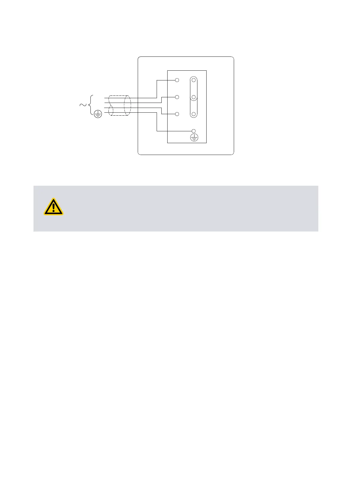
Figure 10 Electrical supply connecon, three-phase motors: 380-415 V 50 Hz and 460 V 60 Hz
3
L1
L2
L3
U1
W2
V1
U2
W1
V2
CS/1120/A
4.9 Connect the pump outlet
WARNING:
Connect the pump outlet to a suitable treatment plant to prevent the discharge of
dangerous gases and vapours to the surrounding atmosphere. Use a catchpot to
prevent the drainage of contaminated condensate back into the pump.
The exhaust system must be congured so that the maximum pressure at the pump
outlet does not exceed 0.5 bar gauge (1.5 bar absolute, 1.5 x 10
5
Pa) at full pump
throughput.
We recommend ng an oil mist lter to the pump outlet in the following
circumstances:
▪ When using the pump with the gas-ballast control open.
▪
When operang the pump with an inlet pressure greater than 10 mbar for
extended periods.
▪ When frequently pumping down from atmospheric pressure.
The mist lter will trap the oil exhausted from the pump: the oil can be reused if it is not
contaminated.
To connect the pump to the outlet accessories or to the exhaust treatment plant:
▪
Connect 15 mm internal diameter vacuum or plasc hose to the outlet nozzle
(Figure: General view of the pump on page 11).
▪
Remove the outlet nozzle and connect to the 3/4 inch BSP threaded hole.
▪
Remove the outlet nozzle and replace it with an NW25 ange adaptor (available as
an oponal accessory, refer to Pump outlet adaptor on page 48) and then connect
to the NW25 ange.
4.10 Gas-ballast inlet connecon
The posion of the gas-ballast inlet is shown in Figure: General view of the pump on
page 11. The gas-ballast inlet has several lters (shown in Figure: Remove/replace the
Page 29
A34310880_T - Installaon