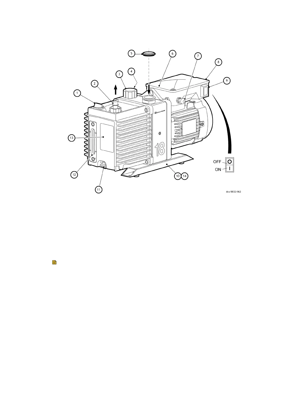
Figure 1 General view of the pump
1. Oil ller 2. Outlet nozzle
3. Gas-ballast control 4. Gas-ballast inlet
5. Centring-ring and O-ring (supplied) 6. Inlet-port (adaptor ange)
7. Cable-gland/Amphenol connector
posion
8. Motor terminal box
9. On/O switch
10. Box secon skids 11. Oil drain-plug (gravity drain)
12. Oil sight-glass 13. Pump idencaon label
14. Oil drip tray
Note:
A pump with a single-phase motor is shown in this gure. The motor shown in this gure
is not representave of the motor used on the E1/E2M18 pumps with Item Numbers
A34317984 and A36317984. On these pumps, Cable-gland/Amphenol connector posion
and On/O switch are transposed, with Cable-gland/Amphenol connector posion being
an IEC60320 16-20 Amp socket.
2.4 Gas-ballast
When using the pump with high vapour throughputs, the gas-ballast facility should be
used to prevent condensaon of the vapours inside the pump. The condensates will
contaminate the oil, will cause performance to deteriorate and may cause corrosion of
the pump mechanism.
Air (or an inert gas) can be introduced into the pump mechanism through the gas-ballast
control (Figure: General view of the pump on page 11).
Page 11
A34310880_T - Introducon