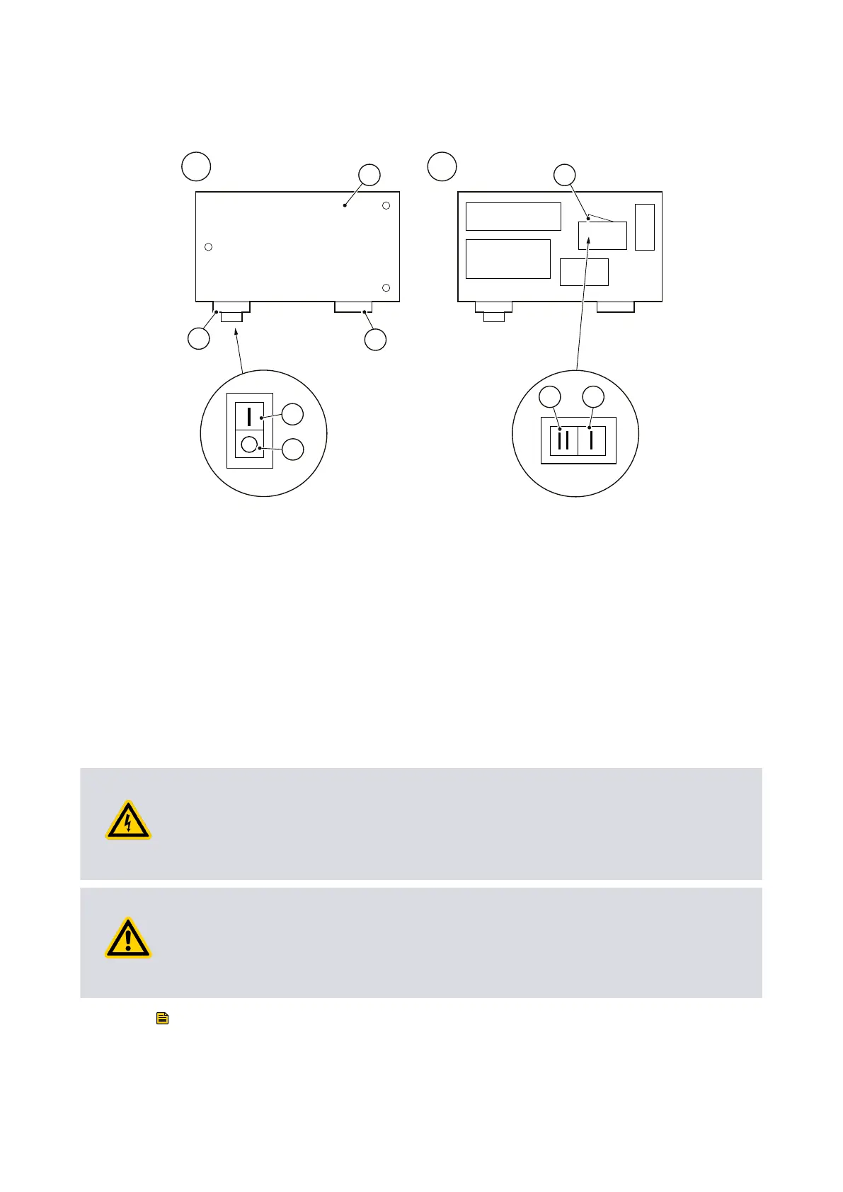
Figure 8 Motor voltage selecon: single-phase motors, 110/200-240 V 50 Hz and
115-120/200-240 V 60 Hz
A. Top view of motor B. Internal view of top of motor
C. On/O switch
A. Top view of motor B. Internal view of top of motor
C. On/O switch
1. Terminal box cover 2. Electrical inlet socket
3. On/O switch 4. Posion 'I' (on)
5. Posion 'O' (o) 6. Voltage selector switch
7. Posion 'II' (high voltage seng
200‑240 V)
8. Posion 'I' (low voltage seng
110‑120 V)
1. Terminal box cover 2. Electrical inlet socket
3. On/O switch 4. Posion 'I' (on)
5. Posion 'O' (o) 6. Voltage selector switch
7. Posion 'II' (high voltage seng
200‑240 V)
8. Posion 'I' (low voltage seng
110‑120 V)
4.7 Electrical installaon: three-phase motors
4.7.1 Connect the electrical supply to the motor
WARNING:
Ensure that the electrical installaon of your pump‑motor conforms with your local
and naonal safety requirements. It must be connected to a suitably fused and
protected electrical supply and a suitable earth point.
CAUTION:
If your pump‑motor can be used with more than one voltage range, you must ensure
that the motor is congured for your electrical supply voltage. If you do not, you may
damage the motor.
Note:
The pump will restart automacally when the electrical supply is restored aer an
interrupon. If you do not want the pump to restart automacally, use electrical control
equipment which must be reset manually.
Page 26
A34310880_T - Installaon