A313-01-880 Issue A
Page 20 © Edwards Limited 2008. All rights reserved.
Edwards and the Edwards logo are trademarks of Edwards Limited.
Installation
3.8.3 Connect the motor thermistors (if fitted)
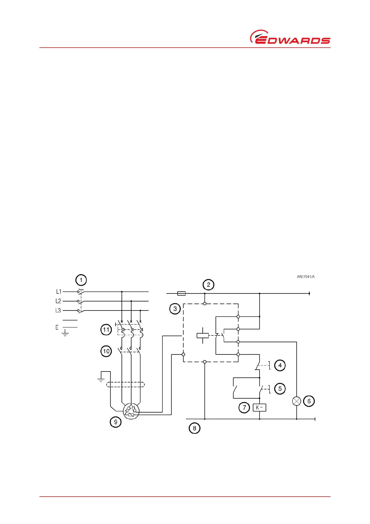
You must connect the thermistor terminals in the motor to a suitable control circuit, to shut down the HV pump
system if the motor temperature is too high. An example control circuit is shown in Figure 4.
You must use a suitable two-wire cable and a suitable cable-gland to connect the thermistors cable (from your control
circuit) to the thermistor terminals in the motor. The cable-gland (and adaptor, if fitted) must provide a protective
seal to IP44 (or higher), as defined by IEC 529. Refer to the Motor Manual supplied with your motor for the sizes of
the thermistor cable-gland holes in the motor.
Make the thermistor connections in the motor as described in the Motor Manual supplied.
3.8.4 Connect the motor thermostats (if fitted)
You must connect the thermostat terminals in the motor to a suitable control circuit, to shut down the HV pump
system if the motor temperature is too high. An example control circuit is shown in Figure 4.
You must use a suitable two-wire cable and a suitable cable-gland to connect the thermostats cable (from your
control circuit) to the thermostat terminals in the motor. The cable-gland (and adaptor, if fitted) must provide a
protective seal to IP44 (or higher), as defined by IEC 529. Refer to the Motor Manual supplied with your motor for the
sizes of the thermostat cable-gland holes in the motor.
Make the thermostat connections in the motor as described in the Motor Manual supplied.
3.9 Earth (ground) connection
Note that:
We recommend that you connect the booster pump to a suitable factory/plant earth (ground).
Figure 4 - Example electrical control circuit
1. Electrical supply isolator
2. +ve control side
3. Thermistor/thermostat relay
4. Stop switch
5. Start switch
6. Fault indicator lamp
7. Pump contactor
8. 0 V control side
9. Pump motor
10.Contactor
11.Circuit breaker