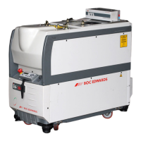
1. FDP pump
2. Exhaust-purge pipeline
3. 3/4-dilution purge pipeline
4. 2/3-cooling purge pipeline
5. Inlet-purge pipeline
6. Shaft-seals purge pipeline
7. Pressure transducer (exhaust-purge)
8. Pressure-relay (exhaust-purge)
9. Gas Module manifold
10.Variable restrictor (3/4-dilution purge)
11.Variable restrictor (2/3-cooling purge)
12.Variable restrictor (inlet-purge)
13.Variable restrictor (shaft-seals purge)
14.Variable restrictor (exhaust-purge)
15.Solenoid-valve (3/4-dilution purge)
16.Solenoid-valve (2/3-cooling purge)
17.Solenoid-valve (shaft-seals purge)
18.Variable restrictor (dilution purge control)
19.Solenoid-valve (dilution purge control)
20.Solenoid-valve (inlet-purge)
21.Pressure transducer (shaft-seals purge)
22.Solenoid-valve (exhaust-purge)
23.Mass flow transducer
24.Pressure regulator
25.Check-valve
26.Nitrogen supply inlet

 Loading...