© Edwards Limited 2009. All rights reserved. Page 21
Edwards and the Edwards logo are trademarks of Edwards Limited.
Technical Data
A533-23-880 Issue C
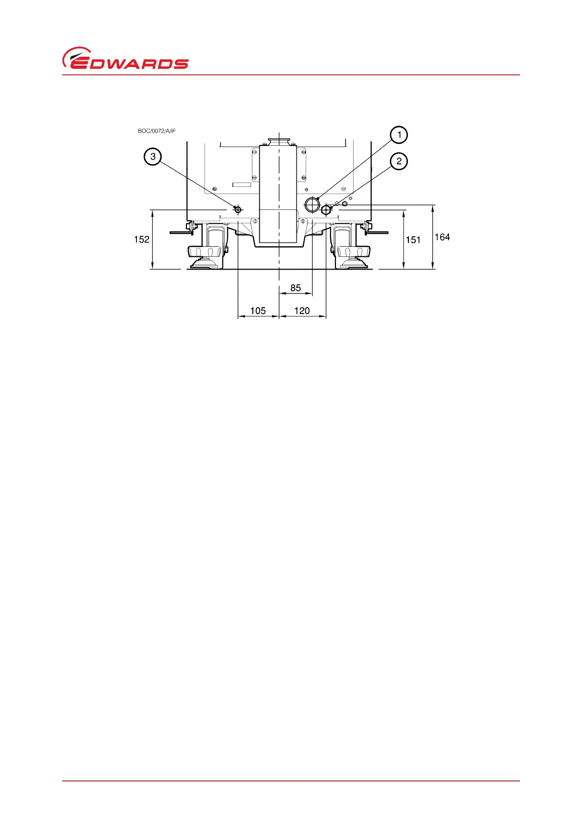
Figure 11 - Services connections dimensions (mm)
2.3 Temperature control system
2.4 Cooling Water Supply
Pumps are supplied with quick release connectors. The water supply should be provided with an isolator.
Note: Use treated water or non-corrosive industrial water to cool the iF system.
FDP pump shut-down thermistor
Type Negative Temperature
Coefficient thermistor
“Opening” temperature 60±3 °C
“Closing” temperature 50
±4 °C
Thermocouples K type class 1
FDP and HMB motor-protection thermistor type Positive temperature coefficient
Reference temperature HMB 150 °C; FDP 130°C,
(snap switch 155
±3°C)
Compliant with IEC 34-11 (BS4999 part III)
Water flow-switch Closed when system flow > 6 l min
-1
(HMB flow > 2 l min
-1
)
Maximum supply pressure 100 psig (6.9 bar, 6.9 x 10
5
Pa)
Typical pressure differential across supply and return
*
iF1800 20 psi (1.34 bar, 1.34 x 10
5
Pa)
Minimum flow rate required for reliable iF system operation
iF1800 6 l min
-1
1. Cooling-water outlet
2. Cooling-water inlet
3. Nitrogen inlet
 Loading...

