A590-00-880 Issue D
Page 4 © Edwards Limited 2008. All rights reserved.
Edwards and the Edwards logo are trademarks of Edwards Limited.
Introduction
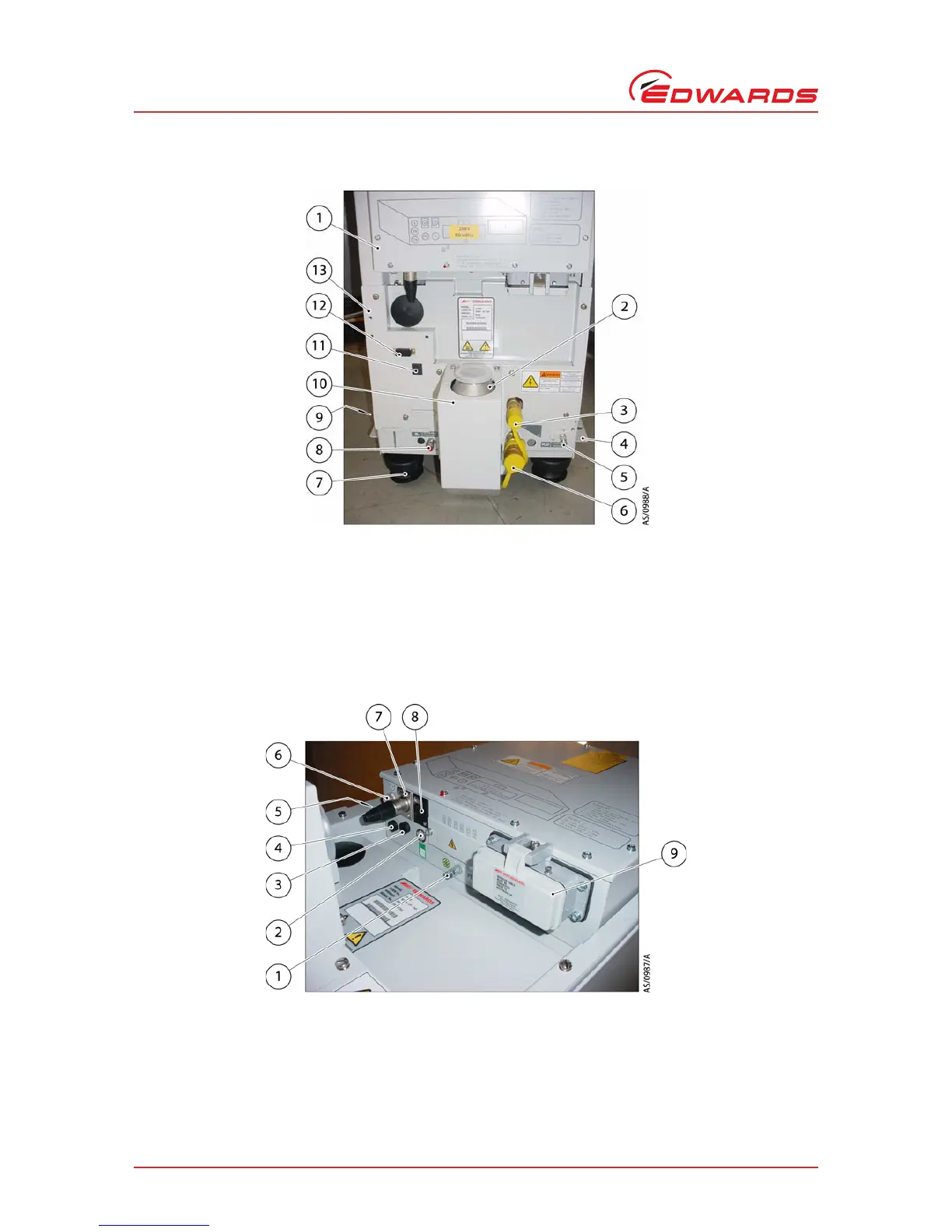
Figure 3 - The controls/connectors on rear of pump
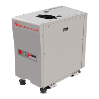
Figure 4 - The controls/connectors on electrics box
1. Electrical box
2. Exhaust check valve
3. Cooling-water supply connection
4. Seismic bracket (4 off)
5. RF earth (ground) stud M6
6. Cooling-water return connection
7. Levelling feet (4 off)
8. Nitrogen purge port
9. Castor (4 off)
10. Exhaust enclosure
11. Active gauge connection
12. iTIM connection
13. Rear cover
1. Protective earth (ground) stud M5
2. Exhaust gas outlet connection
3. d.c. Electrical supply fuse holder (F10)
4. Emergency stop fuse holder (F9)
5. Tool interface module fuse holder (F8)
6. Rear Power on lamp
7. EMS/Tool interface module connection
8. LON module connection
9. Electrical supply connection