LRP200000201 Issue A
Page 8 © Edwards Limited 2016. All rights reserved.
Edwards and the Edwards logo are trademarks of Edwards Limited.
Installation
3.3 Locate the pumping system
Failure to obey the installation instructions listed in the following section and on installation drawing(s) supplied
with the system may result in damage to the system and reduce system or individual component lifetime.
1. Ensure that the operating location is clean and free from debris, oil and dripping water and is not subjected to
adverse environmental conditions. Refer to Table 3 for operating and storage conditions.
2. Provision must be made for correct pipeline arrangements and access to the equipment for lifting,
commissioning and operation (including free airflow around the electric motors), and routine servicing. Refer to
the installation drawing(s) and manufacturer's instructions supplied with the pumping system.
3. Ensure the concrete foundations are of a mass that is at least 150% of the operating mass of the pumping system.
Concrete strength shall be at least according to class C40/50 as specified in EN 206, (40 MPa at 28 days). The
foundation pad should extend to 150 mm beyond the base frame that it supports. The top surface of the
concrete must be level, with a maximum flatness deviation of 2 mm.m
-1
as measured using a 1 metre straight
edge so as to avoid excessive shimming. The top surface must also be clean and free from debris, grease and oil
before installation of the base frame commences.
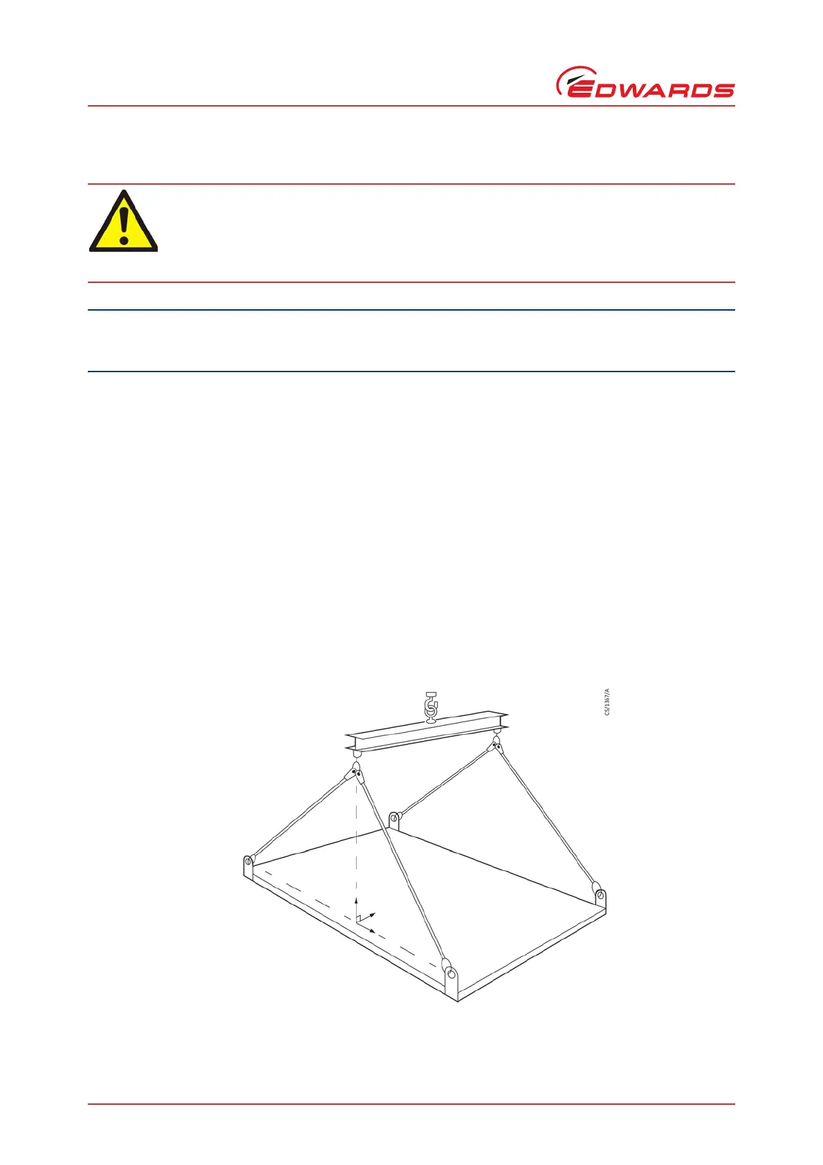
4. The pumping system is provided with suitable lifting eyes or lugs to enable safe positioning. Check that the lugs
and shackles are lifted at the correct angle (refer to Figure 1) to prevent the lugs being bent or damaged (in
some cases this may necessitate the use of a lifting frame).
Figure 1 - Lifting technique
Ensure 90° lift perpendicular to lifting lug axis.
Use suitable lifting equipment to move the pumping system. All lifting operations must utilise
identified lifting points or lugs and an appropriate spreader bar. Refer to the installation drawing
supplied with the liquid ring vacuum pumping system for key dimensions, terminal connections and
approximate dry and operating weights.