LRP200000201 Issue A
Page 10 © Edwards Limited 2016. All rights reserved.
Edwards and the Edwards logo are trademarks of Edwards Limited.
Installation
Cooling liquid inlet/outlet.
Seal liquid drain.
Take note of the following when connecting the pumping system to the process:
Refer to the installation drawing supplied with the pumping system for specific pipeline requirements.
The pumping system is supplied with protective covers on all connections. Please remove these prior to
connecting to the process system pipelines.
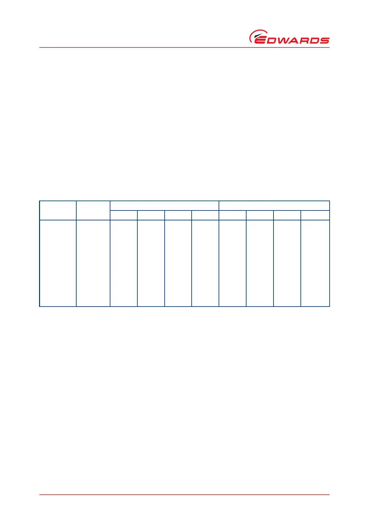
Do not exceed the maximum allowable forces and moments given in Table 8. All connections must be strain
free.
The pipelines must have an internal diameter not less than the terminal connection diameters.
Ensure all the pipelines are dry, clear of debris and free from blockages before connecting them to the
pumping system.
Support all pipelines close to the pumping system. Allow for thermal expansion and flexibility.
3.4.2 Connect process inlet and outlet
Using a suitable gasket as a seal, connect the process pipeline to the process inlet and outlet of the pumping system.
For optimum performance, ensure that the pipeline connected to the process is as short as possible and
avoids restrictions and liquid hold up points.
Install a suitable temporary process inlet filter to prevent particles larger than those specified in the
bareshaft liquid ring pump instruction manual, refer to Section 1.2.7, from entering the liquid ring pump.
Ensure that the maximum outlet pressure specified in the bareshaft liquid ring pump instruction manual,
refer to Section 1.2.7, cannot be exceeded.
3.4.3 Connect seal liquid initial fill and make-up
Using a suitable gasket as a seal, connect the seal liquid make-up to a suitable water supply. Refer to Section 2.5 for
service requirements.
3.4.4 Connect cooling liquid
If installed, using a suitable gasket as a seal, connect the heat exchanger cooling liquid connections to the cooling
liquid circuit.
Table 8 - Maximum allowable forces and moments on nozzles
NPS inch NB mm
Forces kN Moments kN.m
FX FY FZ FR MX MY MZ MR
0.5 12.70 0.03 0.08 0.07 0.11 0.06 0.03 0.03 0.07
0.75 19.05 0.05 0.13 0.10 0.17 0.08 0.04 0.04 0.10
1 25.40 0.07 0.17 0.13 0.22 0.11 0.06 0.06 0.14
1.5 38.10 0.10 0.25 0.20 0.34 0.17 0.08 0.08 0.21
2 50.80 0.13 0.33 0.27 0.45 0.22 0.11 0.11 0.27
2.5 63.50 0.17 0.42 0.33 0.56 0.28 0.14 0.14 0.34
3 76.20 0.20 0.50 0.40 0.67 0.34 0.17 0.17 0.41
4 101.60 0.27 0.67 0.53 0.90 0.45 0.22 0.22 0.55
5 127.00 0.33 0.84 0.67 1.12 0.56 0.28 0.28 0.69