© Edwards Limited 2014. All rights reserved. Page 9
Edwards and the Edwards logo are trademarks of Edwards Limited.
INSTALLATION
D397-51-880 Issue E
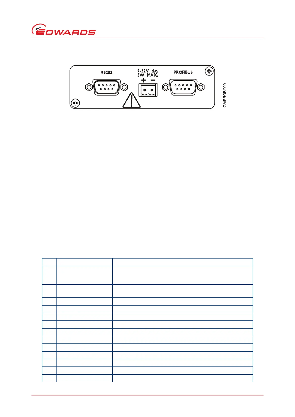
Figure 7 - Profibus module rear connections
Take care during cable installation that all electrical cables are safely secured and cannot present a trip hazard.
3.4 Bus termination
Bus termination is not supplied with the module, but must be used as for a normal Profibus DP system. Bus
termination must be used at both ends of the Profibus trunk and not anywhere else. If the module is placed at one
end of the trunk a connector containing the standard termination resistors should be used. The appropriate 5 V and
0 V signals are supplied on the standard pins for this purpose.
3.5 SCU-750 control unit set up
The control unit command interface and communication parameters must be set up. The procedure for how to do
this is detailed below:
1. Ensure the small slide switch on the front of the control unit labelled "REMOTE" is set to the ON position.
2. Enter the "Parameter Set Mode" by pressing the SELECT and UP switches simultaneously.
3. For each menu item the options can be seen and changed by pushing the UP and DOWN buttons. When the menu
item parameter is set to the desired option press the ENTER button, which will temporarily set that parameter
to the value selected and immediately move to the next parameter.
4. Follow this process for all 13 parameters as shown in Tabl e 5.
Table 5 - SCU-750 control unit command interface and communications parameters
Parameter Value to set
1 Remote mode RS232/485 Com. Note: DO NOT SET RS232/485 Modbus or Lonworks
or I/O Remote. This is the only parameter which will not be at the
factory default value.
2 Speed Setpoint Value in RPM. This must not be greater than the maximum value for
the pump.
3 TMS function Disable - unless the system has this additional hardware.
4 Inhibit Command Disable
5 Leak valve option Disable
6Second Damage limit Enable
7 Baud Rate 9600
8 Bit Length 8
9Stop bit 1
10 Parity None
11 Driver Type RS232
12 Node address Not important
13 Storage Yes - Read instructions below
 Loading...


