E F A P O W E R EV- H C - I N S T A L L A T I O N A N D U S E R M A N U A L
15 | 28
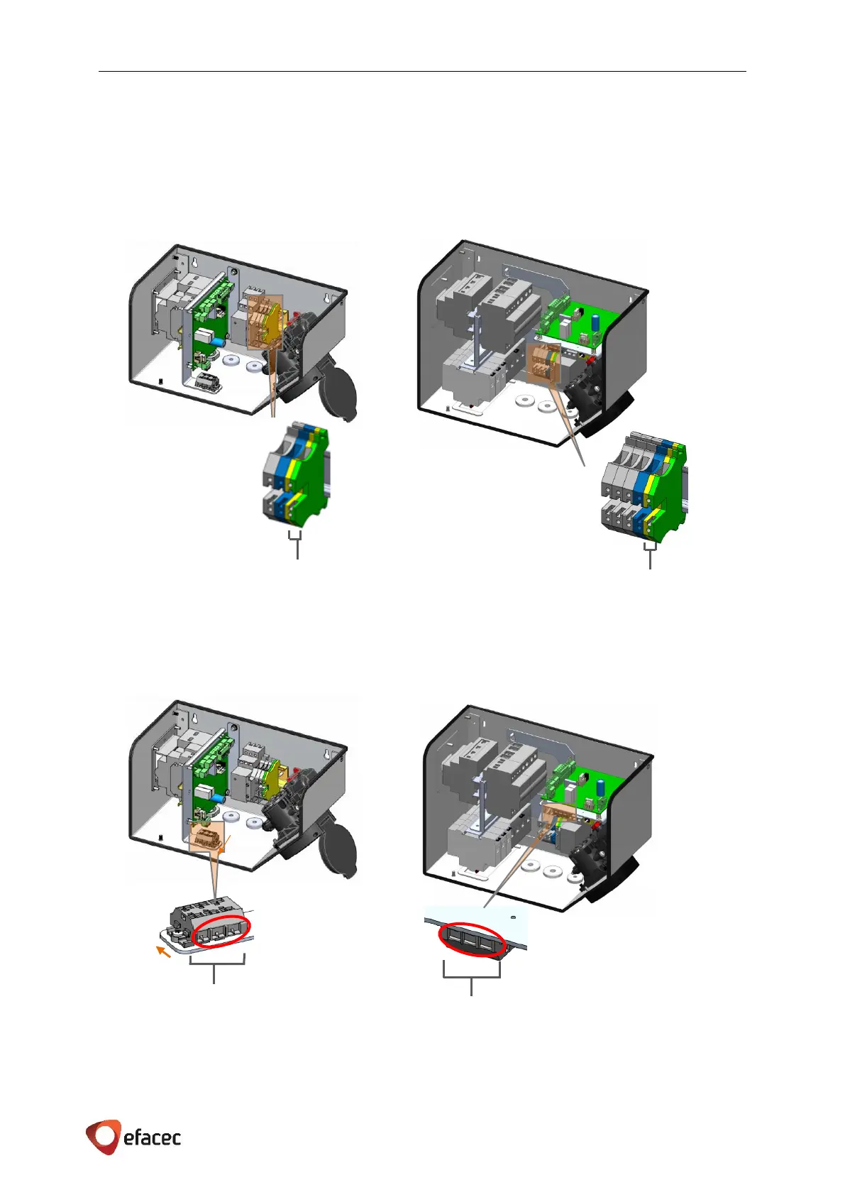
5.3.4.3 PROTECTIVE GROUND
The metallic structure is connected to the protective earth connection, as shown in Figure 13, which should be
interconnected with the low voltage switchboard earth connection.
Cable section of protective earth line, depending on the power rate of EV-HC, can be consulted in Table 3 on
page 9.
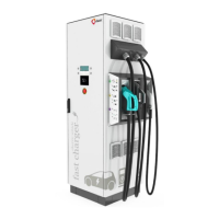
5.3.4.4 COMMUNICATIONS (IF APPLICABLE)
When applicable, the communications on the EV-HC shall be done through X2 double terminal (marked with a
red circle), represented in both EV-HC boxes on the next figure.
NOTE: The following communication scenarios are going to be represented on the one phase EV-HC box,
although they are valid also for the three phase EV-HC box.