Do you have a question about the efacec EFAPOWER EV PC G2 and is the answer not in the manual?
Details the technical specifications of the EFAPOWER EV-PC Public Charger station, including input, output, and mechanical properties.
Lists the applicable standards and regulations that the EFAPOWER EV-PC station complies with for different markets (CE, ETL, GB).
Outlines the environmental conditions necessary for the reliable operation and longevity of the EFAPOWER EV-PC Station.
Specifies local environmental factors like temperature, clearance, and input power cable requirements for installation.
Provides checks for site access, clearance compliance, and distance between units for proper installation.
Details the necessary preparations for the installation site, including wiring and infrastructure.
Explains the upstream wiring schemes and circuit breaker recommendations for CE, GB, and ETL units.
Guides on preparing the mounting surface, whether floor or wall, ensuring proper installation.
Lists the required fasteners, tools, and end terminals needed for installing the EFAPOWER EV-PC Station.
Final checks to ensure appropriate upstream protection and a leveled surface for the charging station.
Provides instructions for safely handling, moving, and positioning the EFAPOWER EV-PC Station before installation.
Information on how the EFAPOWER EV-PC Station is packaged for shipment, detailing unit dimensions.
Guidelines for visually inspecting the unit for damage, condition, and proper ground connection after unpacking.
Instructions for physically moving the unit, noting its weight and the need for two people.
Covers general assembly and placing instructions, including wall mounting and floor anchoring.
Details the drilling layout and methods for securely mounting the EV-CW and EV-SW units on a wall.
Provides drilling layout and anchor point details for fixing the EFAPOWER EV-PC to the floor using a pedestal.
Critical instructions for connecting power cables by qualified personnel, emphasizing safety precautions.
Explains the interconnection of the earth terminal to the switchboard ground connection for safety.
Details the Ethernet cable connections required for linking Central and Satellite units in a network.
Checks to perform before switching on the unit, including cable tightening, ground resistance, and supply voltage.
Crucial safety instructions and procedures for safely switching on the EFAPOWER EV-PC Station.
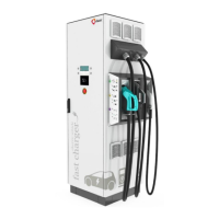
Identifies and describes the different types of output connectors and outlets available on the EV-PC station.
Details the Type 2 outlet, including its availability for specific power outputs on CE marked units.
Describes the Type 1 connector, its availability for CE units, and for ETL units with specific power ratings.
Details the Type 2 connector, specifying its availability for various power rates on CE marked units.
Describes the Type GB connector and its availability for specific power outputs on GB marked units.
Details the CE/7 outlet, indicating its availability for a specific power output on CE marked units.
Provides guidance on the operational sequences and LED status signals during charging.
Explains the user interfaces and charge vehicle interfaces for EFAPOWER EV-PC units equipped with sockets.
Illustrates the sequence of user interfaces during the charging process for units with sockets.
Shows the user interfaces and sequences when the charging process concludes for socket units.
Details the user interfaces and charge vehicle interfaces for EFAPOWER EV-PC units equipped with plugs.
Illustrates the sequence of user interfaces during the charging process for units with plugs.
Shows the user interfaces and sequences when the charging process concludes for plug units.
Covers regular inspections and checks to ensure the EFAPOWER EV-PC's lifetime and reliability.
Specific maintenance actions for the internal battery, if applicable, as per the battery manual.
Provides guidance on diagnosing and resolving common issues, error messages, and LED indicators.
| Product Type | Battery Charger |
|---|---|
| Input Frequency | 50/60 Hz |
| Efficiency | >95% |
| Operating Temperature | -25°C to +50°C |
| IP Rating | IP54 |
| Input Voltage | 400 V AC |
| Communication Interface | OCPP 1.6 |
| Cooling Method | Forced air cooling |
| Protection Features | Overvoltage, overcurrent, short circuit |