E F A P O W E R E V - PC - I N S T A L L A T I O N A N D U S E R M A N U A L
10 | 37
5.2 SITE PREPARATION
Once the local conditions have been verified, it is time to prepare the site for the installation of the EFAPOWER
EV- PC Station.
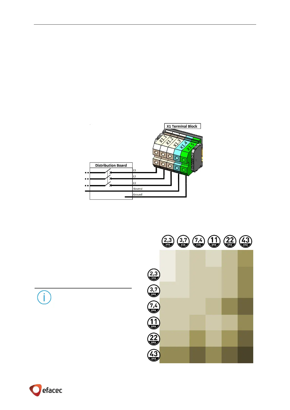
5.2.1 UPSTREAM WIRING INFORMATION
Depending on the configuration of the EFAPOWER EV-PC, the station may have different wiring schemes as
represented in the following three figures.
CE AND GB MARKED UNITS:
• Three phase input connection for CE and GB marked units:
.
Figure 7 - EFAPOWER EV-PC CE/GB Wiring Information (Three-Phase)
Depending on the configuration of the outputs (of
the units) we can have several scenarios for the
circuit breaker to be installed in the distribution
board for each Unit. The appropriate circuit
breaker is represented in Table 3.
Efacec advises a Residual Current Device (RCD)
2P/4P Type AC or 2P/4P Type A, higher than
300mA, to ensure the upstream selectivity. All
local codes shall be taken into consideration.
NOTES
Even if the same Unit side has two outputs
(2,3kVA + any other power rate) the Table 3 is
valid because only one output will work at a time.
In areas with frequent thunderstorms, we advise
to add transient voltage surge suppression (TVSS)
at the service panel for all circuits.