18/32
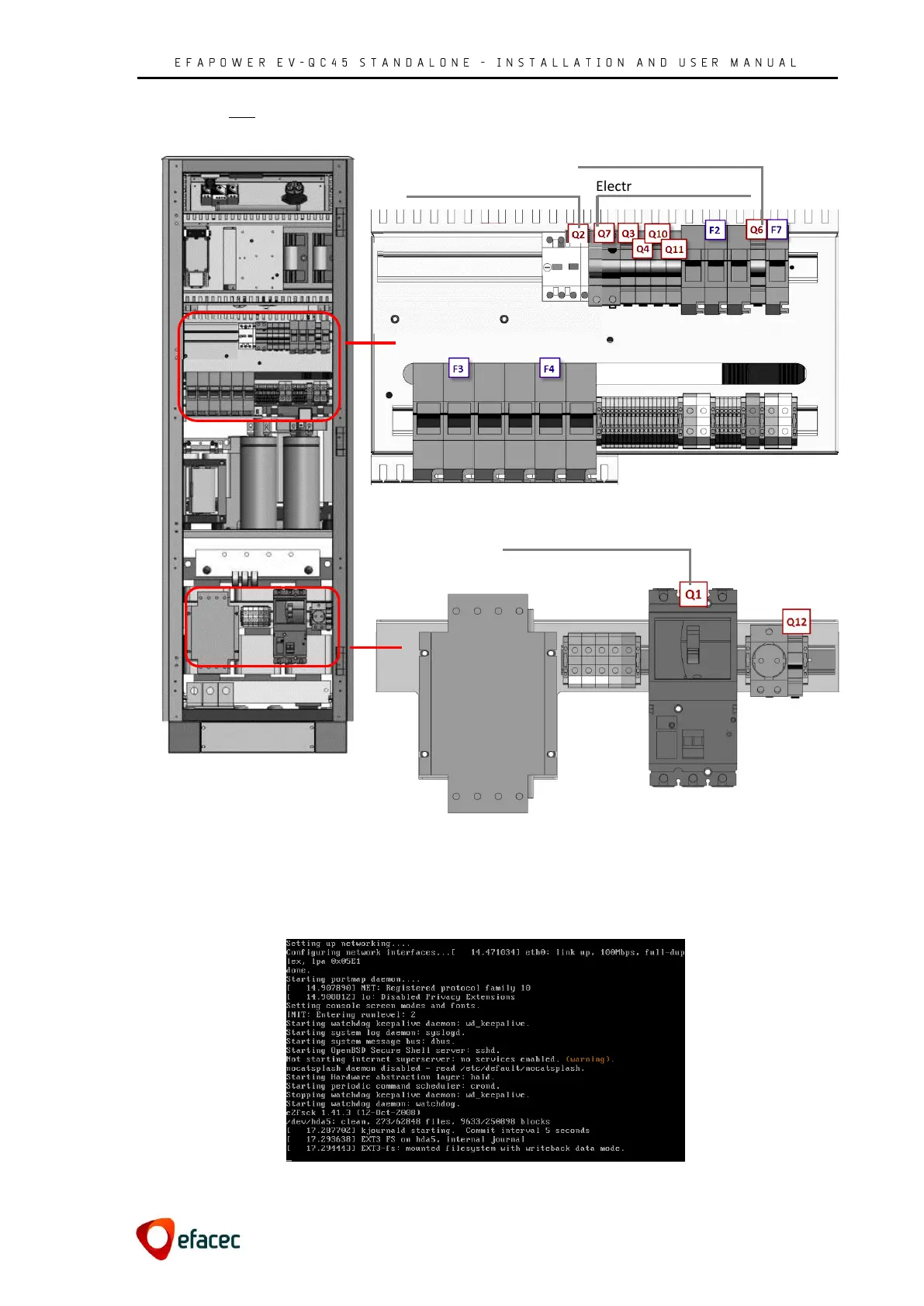
EV-QC45 UL components layout
NOTE: if any of the following events do not happen, please consult Section 8.1 Power up errors.
The display will show the following image during the boot-up process of the operating software:
Figure 21 - EFAPOWER EV-QC45 Initialization
DC output – power main input
Figure 19 - EV-QC45 UL interior front view
Figure 18 – UL Input Plate
Output contactors command
230V auxiliary power supply