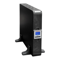
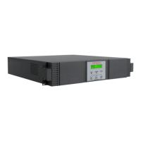
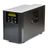
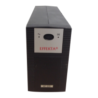
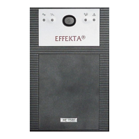
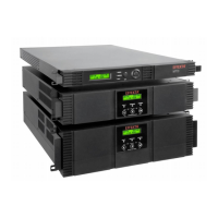
All operation and display components for the device are reduced to the control
panel (PANEL) which can be obtained on the front of the device. The control
panel (A) makes a clear display of all status data or device information and the
operation of the UPS (system) possible.
In addition to the information displayed, several operation, warning and alarm
messages and key activation are acoustically supported by the built-in signal
generator (BUZZER). Please see 8 Me actions for the coding of the acoustic
messages.
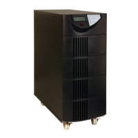
Some heat loss naturally can arise during the operation of the UPS which must
be convectively lead away. There are ventilation ducts available for this which
enable a sufficient airflow in the longitudinal direction of the device. The
integrated fans (2) assist the circulation when necessary.
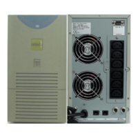
The ports and interfaces for the device are marked accordingly and described
further under 5 Installation and connection of the UPS.
In the standard version, the system has a by-pass switch for maintenance work
(MAINTENANCE). Generally, we, however, recommend external manual by-
pass for use. This BY-PASS switch is independent from the UPS variant and,
when switched on, builds a bridge between the mains power supply and the
loads. At the same time, the UPS is disconnected from both the input and output
sides and thereby disconnected from the installation. Maintenance work can
now be performed without difficulty. For this, see also chapter 15.3 External
by-pass.