- PF321A6012
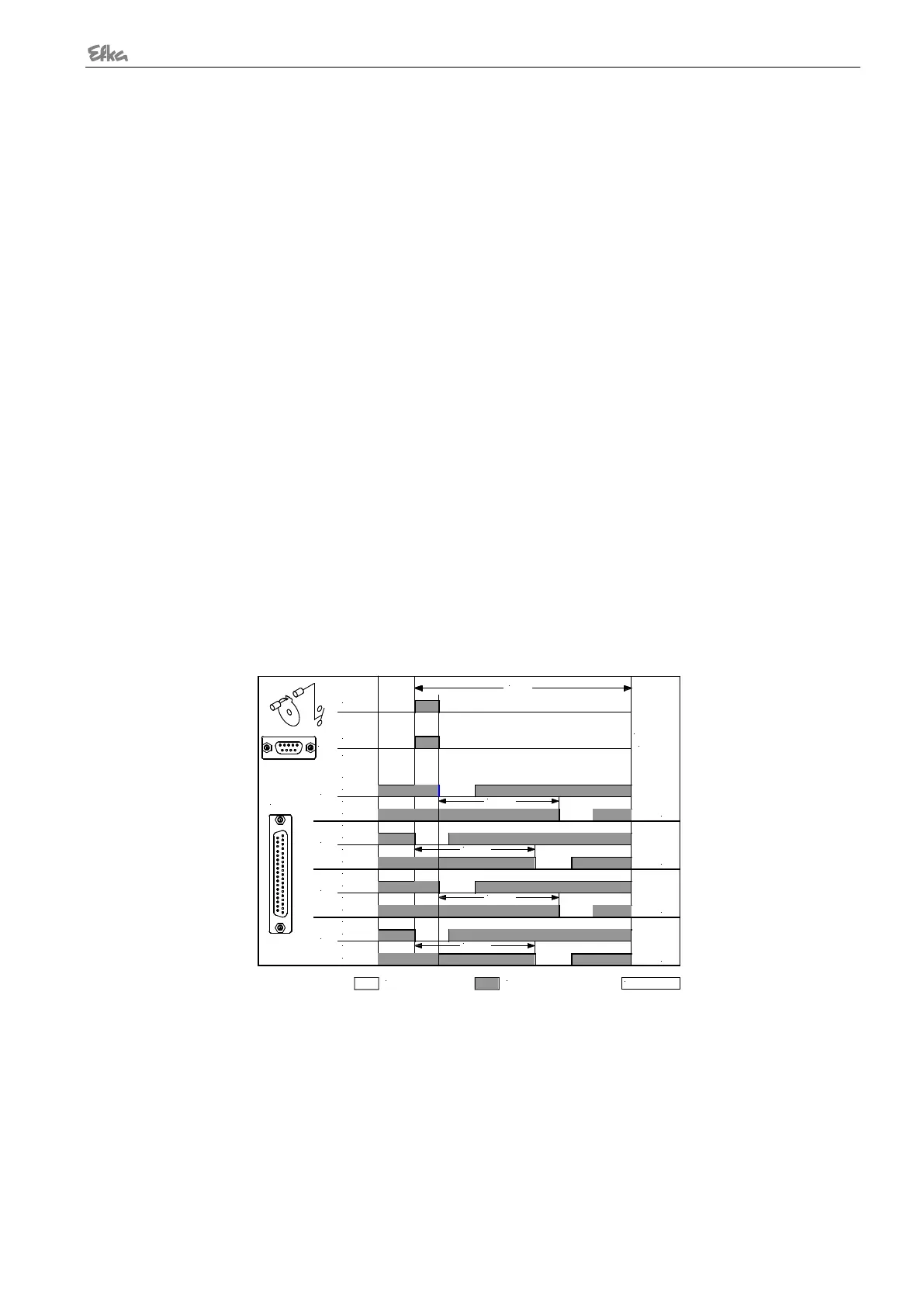
Connection of a sensor (N.C. function) e. g. light barrier or proximity switch to socket B18/7.
The following settings must be made using parameter 270:
- The positions are generated using the transmitter incorporated in the motor and can be set
using parameter 171.
- Setting the sensor to position 2.
- Position 1 is set according to the angular degree setting by means of parameter 271.
- Start measuring from trailing edge position 2.
- 0V at input B18/7 (inside of the window)
- +5V at input B18/7 (outside of the window)
- Setting the sensor to position 2.
- Position 1 is set according to the angular degree setting by means of parameter 271.
- Start measuring from leading edge position 2.
- Input and output level as with setting "1"
- Setting the sensor to position 1.
- Position 2 is set according to the angular degree setting by means of parameter 271.
- Start measuring from trailing edge position 1.
- Input and output level as with setting "1"
- Setting the sensor to position 1.
- Position 2 is set according to the angular degree setting by means of parameter 271.
- Start measuring from leading edge position 1.
- Input and output level as with setting "1"
- No position sensor available. The drive stops unpositioned. The thread trimmer function is
suppressed with this setting.
- The positions are determined by preset values. The reference position must be correctly set
for this purpose. In machines with position sensors incorporated in the handwheel the
reference position is determined by mechanical adjustment. In all other cases the reference
position must be set (see chapter “Setting the Reference Position”) in order for the angles
preset by machine select for positions 1 and 2 to be correct. If necessary, the preset values
can be adapted as described in chapters “Setting the Positions”.
= 0V
OUT
OUT
OUT
OUT
ST2
IN
POS1
POS2
ST2/21
POS1
ST2/20
POS2
ST2/21
ST2/20
POS2
ST2/21
POS1
ST2/20
ST2/20
POS1
POS
B18/7
POS2
ST2/21
SEN
= high
0256/SEN-2
Pa 271
Pa 271
Pa 271
Pa 271
360°
270 = 1270 = 3270 = 4 270 = 2
+5V
0V
OUT (position window) = npn transistor (emitter to 0V) is conductive. The width of position window cannot be
adjusted.