85 / EN
Description
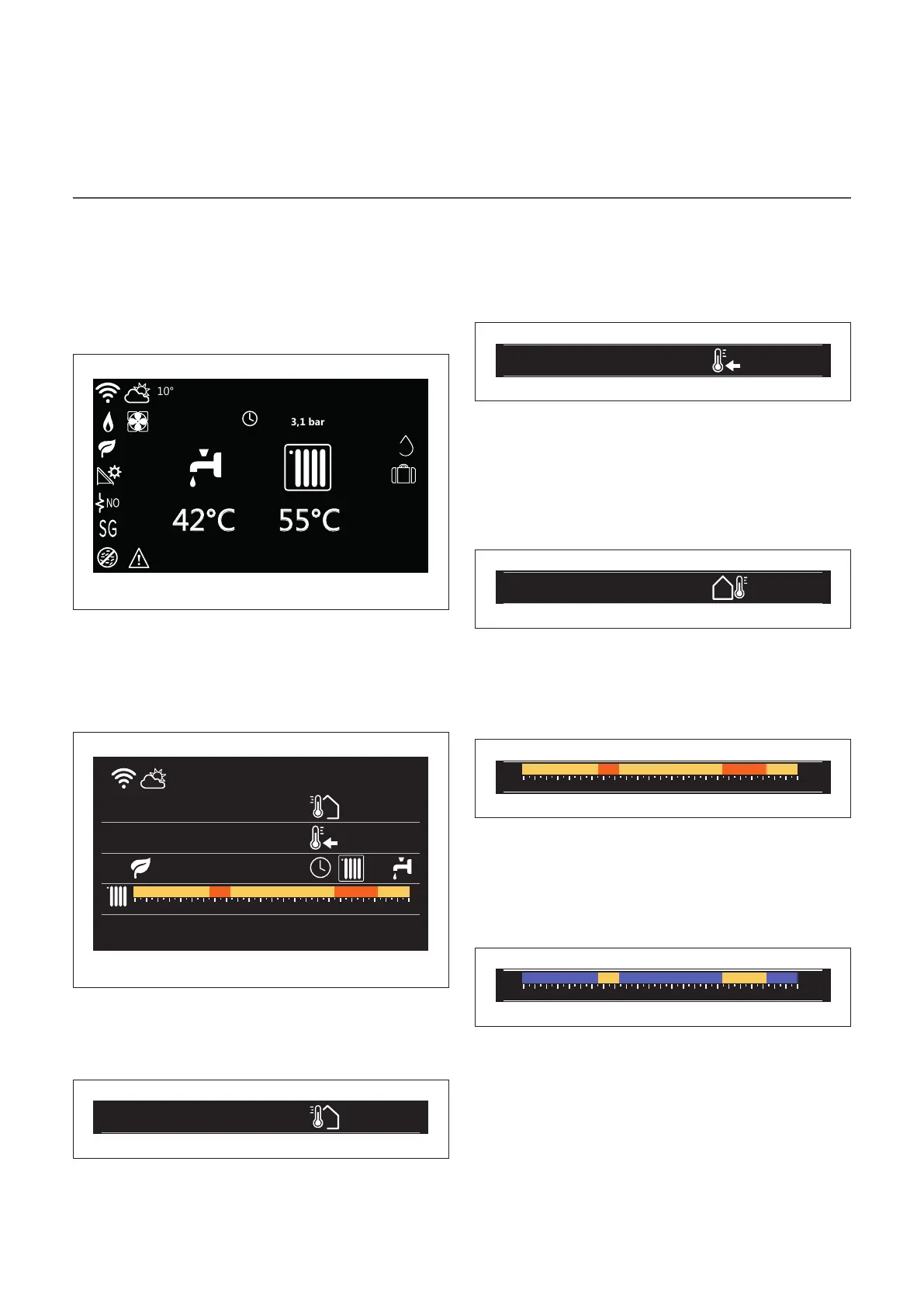
Base home page
The “Base” home page can be selected if the device is config-
ured as a system interface (Zone 0).
The central area shows information about the heating, cool-
ing or domestic hot water modes.
For the meaning of the icons, refer to the paragraph “Com-
plete home page”.
50%
COMFORT
Fr 4-JUN 12:30
Fig. 4
Customizable home page
Fr 4-JUN 12:30
Internal temperature
20°
Required temperature
21°
0 2 4 6 8 10 12 16 20 14 18 22 24
16° 16° 16°20° 20°
Fig. 5
The home page “Customizable” allows the user to view infor-
mation that can be selected in the following options:
Internal temperature
Internal temperature
20°
Required temperature
21°
Outside air temperature
16°
Operation mode
55°C
Fig. 6
If the device is associated with a zone, the room temperature
of the relevant zone is shown. If the device is configured as a
system interface (Zone 0), the room temperature of the zone
defined by the 0.4.0 parameter is shown.
Required temperature
Fr 4-JUN 12:30
Internal temperature
20°
Required temperature
21°
Outside air temperature
16°
Operation mode
55°C
Fig. 7
If the device is associated with a zone, the room set-point
temperature of the relevant zone is displayed. If the device
is configured as a system interface (Zone 0), the room set-
point temperature of the zone defined by the 0.4.0 parameter
is shown.
Outside air temperature
Fr 4-JUN 12:30
Internal temperature
20°
Required temperature
21°
Outside air temperature
16°
Fig. 8
The information is available if an outdoor temperature sensor
is connected or if the “weather from the Internet” function is
activated once the Wi-Fi module has been activated.
Heating time schedule profile
0 2 4 6 8 10 12 16 20 14 18 22 24
16° 16° 16°20° 20°
Fig. 9
If the device is associated with a zone, the heating time
schedule profile of the relevant zone is displayed. If the device
is configured as a system interface (Zone 0), the heating time
schedule profile of the zone defined by the 0.4.0 parameter
is shown.
Cooling time schedule profile
0 2 4 6 8 10 12 16 20 14 18 22 24
19° 19° 19°26° 26°
Fig. 10
Available only for products configured for the cooling mode.
If the device is associated with a zone, the cooling time
schedule profile of the relevant zone is displayed. If the device
is configured as a system interface (Zone 0), the cooling time
schedule profile of the zone defined by the 0.4.0 parameter
is shown.