88 / EN
User Menu
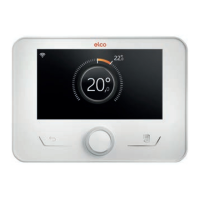
– To access the second page, turn the selector and scroll the
cursor past the last icon of the first page.
Page 2
1
Connectivity
Advanced
settings
System info Screen settings
Fig. 16
– Turn the selector
to highlight the desired menu.
– Press the selector
to access the selected menu.
SYMBOLS Description
Connectivity Allows you to enter the set-
tings of the remote connection
service when a WiFi device
is connected to the bus and
allows you to consult the main
diagnostics information.
System info Allows you to consult the main
diagnostics information.
Screen settings Allows you to configure the
main display settings.
Advanced
Settings
Allows you to access the follow-
ing functions:
- Heating temperature regula-
tion
- Cooling temperature regula-
tion
- Buffer settings
- Advanced settings of the con-
nected devices
- Units of measurement
- Type of time scheduling
- Measured temperature cor-
rection
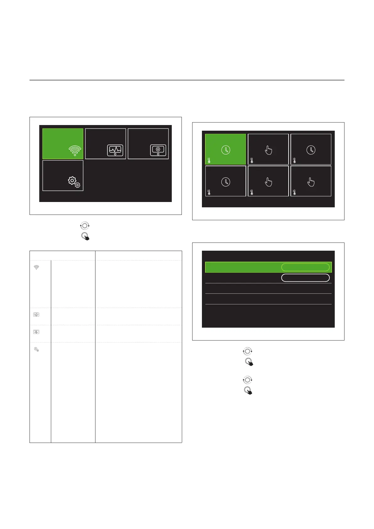
Zones management
The zone menu allows the user to view general information
and to configure the main settings of the zones.
The system allows the user to view up to 6 zones.
20°
,5
20°
,5
20°
,5
20°
,5
20°
,5
20°
,5
21°
,5
21°
,5
21°
,5
21°
,5
21°
,5
21°
,5
SET
SET
SET
SET
SET
SET
Zone 1
Zone 4
Zone 2
Zone 5
Zone 3
Zone 6
Fig. 17
By selecting the single zone, the following information will
be available:
Zone 1
Operation mode
Time program
Zone name Zone 1
Room T setpoint 16,0°C
Time program
>
Fig. 18
– Turn the selector
to highlight the item to be edited.
– Press the selector
to enter the edit mode (the field to
be edited is highlighted in green).
– Turn the selector
to set the desired value.
– Press the selector
to confirm.
OPERATION MODE
Allows for selecting the zone’s operating mode.
– "OFF": the zone is in anti-freeze protection mode. The
room protection temperature is set to 5°C by default.
– "Manual": the set-point temperature is maintained for 24
hours.
– "Time program": the room temperature of the zone fol-
lows the time schedule profile for the zone.