Do you have a question about the elco Firebird FB 4 R LN and is the answer not in the manual?
These instructions for the installation, commissioning and maintenance of the burner are for use by technicians...
The burner is designed to act as a heat source for heating and DHW generation systems...
Key to symbols used in the manual and Other symbols.
It may be hazardous to assign activities to personnel that are not sufficiently qualified.
The following indications refer to “residual risks”, which must be highlighted for the full understanding...
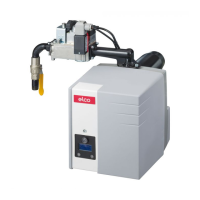
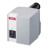
FB 4 R LN is a latest generation single-stage burner fuelled by light oil.
The burner FB 4 R LN includes the following equipments:
Check the identification label of the burner ("Fig. 1").
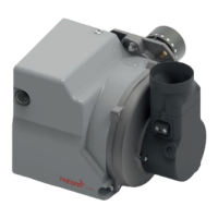
Diagram and list of components of the burner assembly.
Diagram and list of components of the combustion head.
The EBR-M4 control box, controls and monitors the forced draught burner.
Diagram and description of the burner's operating sequence.
Detailed diagrams showing burner dimensions and weight specifications.
Table listing specifications like output, fuel, emissions, and electrical data.
Schematic representation of the burner's electrical connections.
Important safety warnings and precautions for personnel during installation.
Requirements for the environment where the burner is installed.
Checks and considerations for the flue system installation.
List of tools required for burner assembly and operations.
Checks on electrodes and their positioning before burner installation.
Step-by-step instructions for mounting the burner onto the boiler.
Information and warnings regarding fuel oil supply systems and leaks.
Schematic of the oil system's hydraulic connections.
Identification and connection points of the oil pump.
Instructions for connecting fuel delivery and return pipes.
Tables for pipe lengths based on height and diameter.
Safety precautions and procedure for connecting the burner electrically.
Steps and safety warnings for safely removing the burner for maintenance.
Safety warnings and precautions for personnel during commissioning.
List of essential checks to perform before initial burner startup.
Details of factory settings for burner components like nozzle and pump.
Guidance on adjusting CO2 levels based on ambient temperature.
Instructions on adjusting the air flap for optimal combustion.
Procedure for adjusting the burner's operational output.
Steps for setting the oil pressure using the regulator.
Procedure for checking negative pressure in the oil supply.
Instructions for cleaning the pump's internal filter.
Procedure to check and unblock the pump if it is seized.
A checklist to confirm completed commissioning tasks.
Template for recording boiler and burner operational parameters.
Safety warnings and precautions for personnel performing maintenance.
Overview of components crucial for safe burner operation.
Table of components with recommended replacement intervals.
Steps and safety warnings for safely removing the burner for maintenance.
General checks and tasks for maintaining the burner.
Procedure for disassembling and cleaning the combustion head.
Steps to check and adjust the diffuser's position.
Procedure to verify the combustion head's alignment with the nozzle.
Procedure to check and ensure correct electrode positioning.
Steps for replacing the pump coil.
Steps for replacing the burner's capacitor.
Procedure for cleaning the fan wheel and internal rotor.
Parameters to verify after commissioning, cleaning, or maintenance.
General checks and troubleshooting steps for malfunctions.
Flowchart to diagnose and resolve burner issues.
Declaration of conformity to standards and directives.
Information on the suitability of biofuel blends with the burner.
Guidance and precautions for using biofuels.