Do you have a question about the elco Firebird FB 2 K LN and is the answer not in the manual?
General introduction to the manual's purpose and scope for qualified technicians.
Defines the burner's specific application for heating and DHW systems with water as the heating fluid.
Explains the meaning of danger, warning, and caution symbols used in the manual.
Explains symbols related to flammable materials, hot surfaces, personal, and environmental protection.
Outlines necessary qualifications and responsibilities for safe installation, commissioning, and maintenance.
Details critical risks like electrical shock, burns from hot surfaces, and fuel leaks, requiring specific precautions.
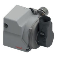
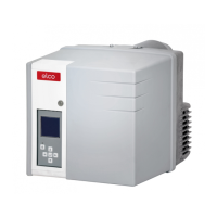
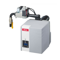
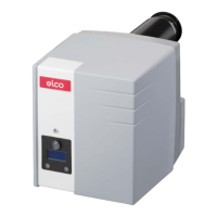
Introduces the FB 2 K LN as a kerosene burner with low NOx/CO emissions and reliable operation.
Lists the included components and accessories provided with the burner unit.
Explains how to read the burner's identification label and its various data points.
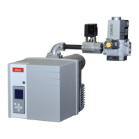
Details the physical components of the burner, illustrated with diagrams for identification.
Describes the function and operation of the microprocessor-controlled EBR-M1 control box.
Illustrates the sequence of operations for startup, running, and shutdown, including safety functions.
Provides detailed physical dimensions and weight specifications for the burner, including packaging.
Lists key technical specifications like burner output, fuel type, emissions, power consumption, and operating temperatures.
Presents the wiring diagram for connecting the burner's electrical components to the control box.
Emphasizes critical safety precautions related to electrical hazards, fuel oil contact, and personnel qualifications.
Specifies environmental requirements and safety warnings for the location where the burner will be installed.
Lists the tools required for assembly, highlighting the utility of the supplied hex key.
Details essential checks, such as electrode positioning and distance, before mounting the burner.
Guides the user through the correct mounting procedure of the burner onto the boiler using flanges and fasteners.
Explains the procedure for safely removing and refitting the burner's protective cover.
Covers safety warnings and installation requirements for fuel oil supply lines, including leaks and tank considerations.
Presents the hydraulic schematic for the fuel oil system, detailing components and flow.
Details the oil pump components and their connections within the fuel system.
Provides guidelines and diagrams for installing the oil feed and suction lines using a one-pipe system.
Offers instructions and diagrams for installing oil feed and suction lines in a two-pipe configuration.
Provides essential safety instructions and requirements for connecting the burner's electrical system to the boiler.
Outlines the step-by-step process for safely disconnecting and removing the burner from the boiler.
Reinforces safety protocols and personnel qualifications required before and during the commissioning process.
Lists critical checks for the burner, boiler, and system readiness prior to initial startup.
Details the factory default settings for burner output, nozzle, and pump pressure.
Explains how to adjust combustion parameters like CO2 based on ambient temperature for optimal performance.
Describes how to adjust the air flap using the hex key to control O2 and CO2 levels.
Guides on adjusting the burner's output by modifying oil pressure and airflow, with safety warnings.
Details the procedure for initial burner start-up, including oil filling and bleeding.
Provides instructions for adjusting burner output and monitoring combustion values.
Details the procedure for setting oil pressure using the regulator and monitoring combustion values.
Explains how to check for maximum permissible negative pressure in the oil supply line.
Describes the process for accessing and cleaning the oil pump filter.
Guides on checking and resolving issues related to pump motor rotation and potential blockages.
Provides a checklist for recording commissioning work and confirming its completion.
Offers a table format to document specific burner and boiler settings and measured values.
Highlights critical safety measures, including electrical hazards, hot surfaces, fuel leaks, and personnel requirements.
Identifies components subject to wear and provides recommended replacement intervals for safe operation.
Provides step-by-step instructions for safely disconnecting and removing the burner for maintenance.
Outlines general maintenance tasks, component checks, and replacement procedures for the burner.
Details the process for disassembling, cleaning, and reassembling the combustion head and its parts.
Explains how to check and adjust the diffuser's position relative to the nozzle for optimal combustion.
Guides on verifying the correct distance between the combustion head and the nozzle.
Describes how to check and ensure the correct distance and centering of the ignition electrodes.
Provides instructions for safely removing and replacing the pump coil if it malfunctions.
Details the procedure for safely disconnecting and replacing the burner's capacitor.
Explains how to clean the fan wheel and internal rotor, checking its positioning.
Lists parameters to verify after maintenance or commissioning to ensure optimal combustion.
Provides initial checks for malfunctions and guidelines on resetting the burner safely.
Offers a visual flowchart to help diagnose and resolve common burner operational issues.
Declares conformity of the burner with relevant European standards and directives.
Specifies the burner's suitability for kerosene with up to 10% biofuel content.
Offers technical considerations and precautions for using biofuels in the burner system.