39
Plug the SUBOUT interface board in J64B on the K3 RF board as shown in Figure 47. J64B is between the
K3 roofing filters and the front panel. Be certain the SUBOUT board is aligned so all pins of P1 are engaged
with J64B.
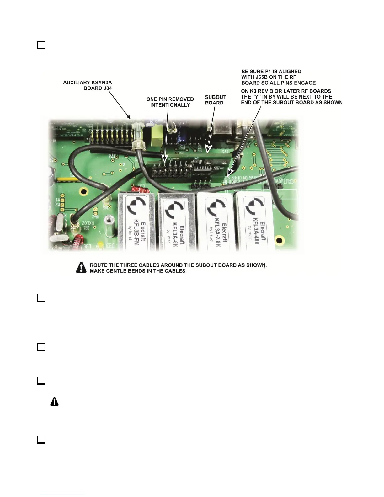
Figure 47. Mounting the SUBOUT Interface Board.
Position the three TMP cables near the SUBOUT board as shown in Figure 47 so they will not interfere
with installing the KRX3A RF enclosure. Note how the cable you attached to J84 on the Auxiliary KSYN3A
board is placed between the roofing filters and the SUBOUT board. Avoid kinking the cables. Arrange them
with smooth bends. You may need to unplug one end of the cable and twist the coax slightly so it will lie in
smooth curves where needed.
If you have the K144XV 2-meter option with the K3EXREF phase lock option installed, connect one 6”
(15 cm) cable to J4 on the Main KSYN3A board (see Figure 48). The other end will be connected to the
K144XV module when you reinstall it later.
Connect the 10” (25 cm) TMP cable you connected to J4 on the Auxiliary KSYN3A earlier to J2 on the
main KSYN3A board (see Figure 48).
That will complete all of the cables shown in Figure 48 except the cable between J83 on the Auxiliary
KSYN3A and J1 on the KREF3 board. This will be installed after the KRX3 enclosure is installed.
You
may wish to remove the existing cable between J2 on the KREF3 board and J83 on the main KSYN3A
board to provide better visibility when installing the KRX3A RF enclosure in the following steps.
Check the position of both the SUBOUT and SUBIN interface boards to be sure they are still fully seated in
their corresponding connectors on the K3 RF board.