40
Check to ensure the battery cover is in place protecting the top of the battery from contact with the KRX3A
enclosure (see Figure 44). The top edge of the battery is the positive terminal, and touching the enclosure during
installation will short-circuit the battery.
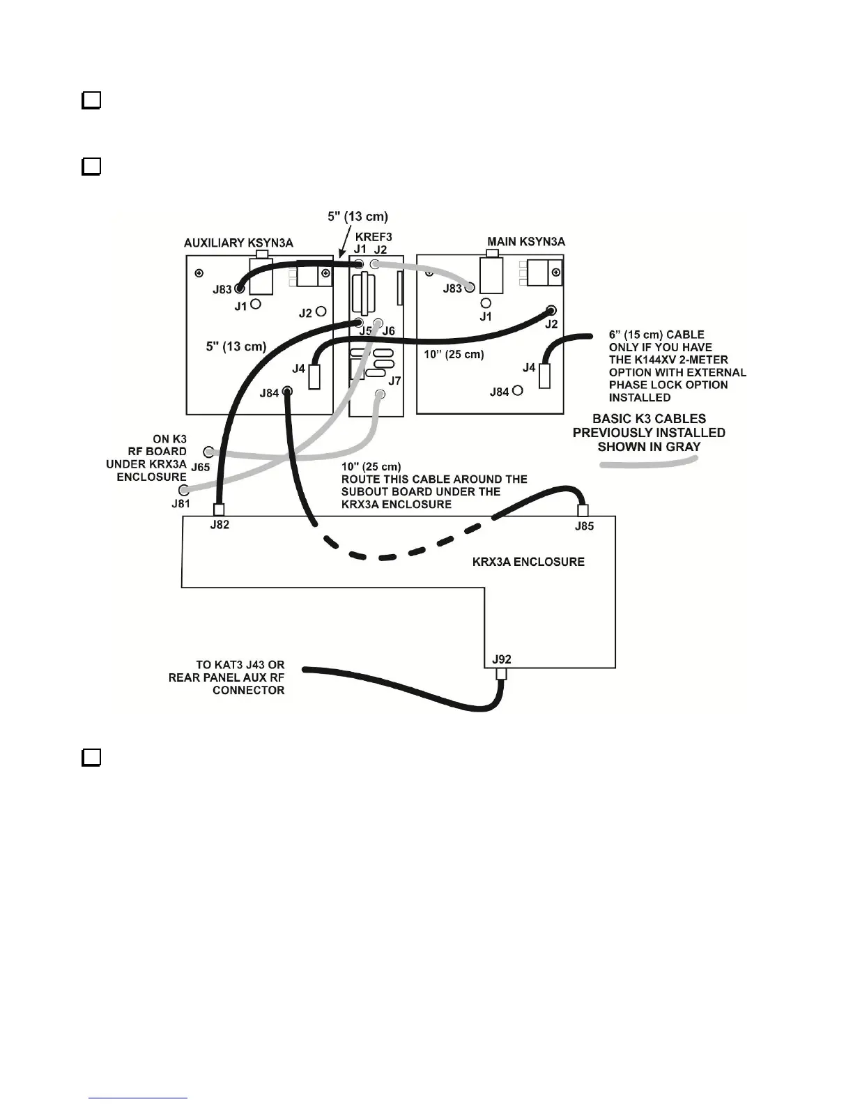
Hold the assembled KRX3A module directly over the K3 and attach the TMP cables to J82 and J85 on the
module as shown in Figure 48.
Figure 48. TMP Cable Connection Pictorial Diagram.
If installed, attach the antenna cable connected to either the KAT3 or to the AUX RF BNC jack on the rear
panel to J92 at the end of the KRX3A as shown. This connector is angled upwards to provide clearance between
the connector and the KIO3 board when the unit is installed. Be certain the TMP connector is fully inserted in
J92. When the KRX3A module is installed the clearance between the connector and the nearby KIO3 board is
very small.