ATS-5X User Manual Page 34 of 44
both simultaneously in a loop test. When acting as a transmitter, a fixed set of discrete tones is sent simultaneously in a
continuous manner. A number of measurements are performed on the receiver signal and displayed on the screen in
numerical and graphical format. The measurement results can be saved at any time to a USB drive.
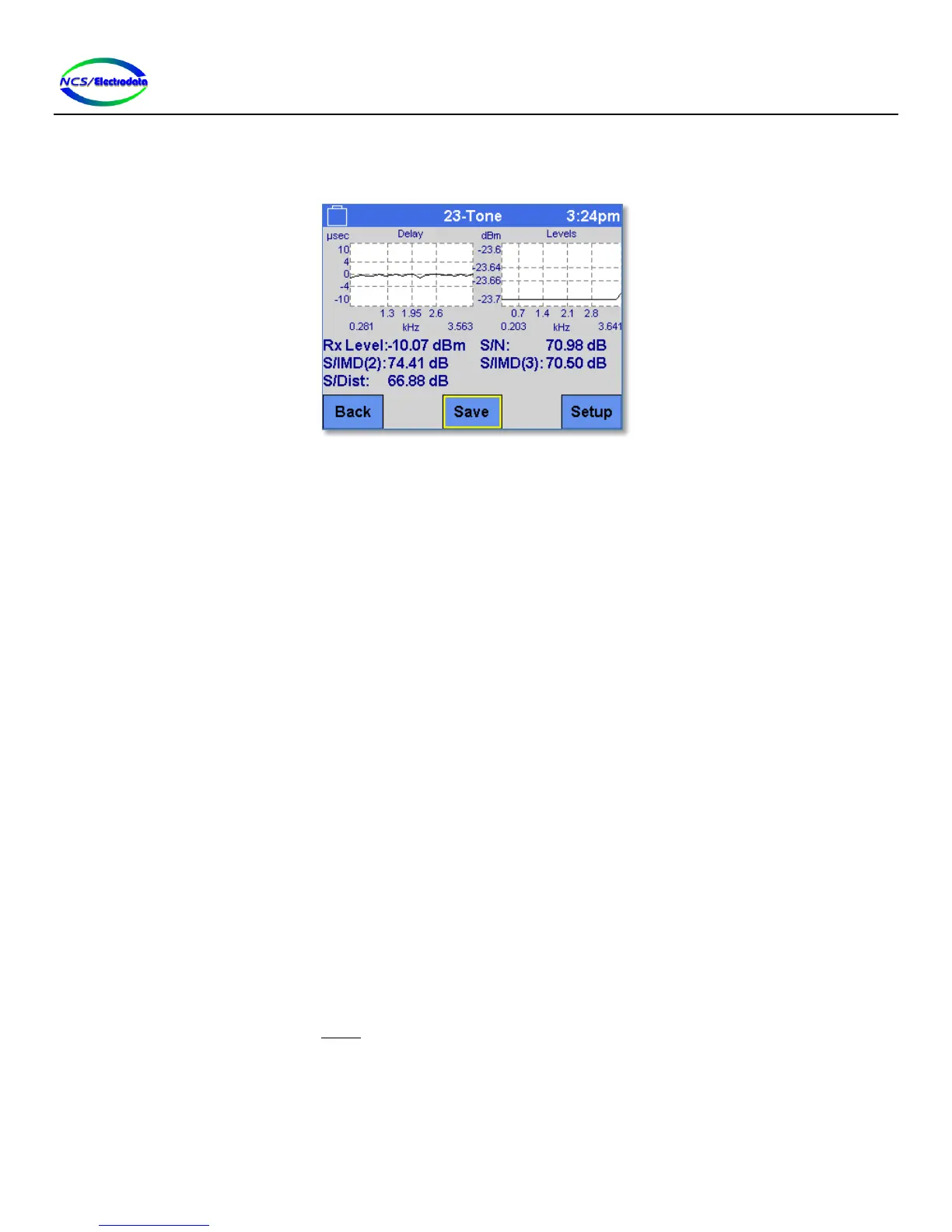
Figure 45 – 23-Tone Measurement Screen
2.7.8.2 Setup
There are no restrictions on the line interface setup for this measurement.
The following transmit modes are permitted for this measurement:
Off
23-Tone
2.7.8.3 Measurements and Controls
The following measurements are shown on the screen and updated continuously:
Delay: A graphical representation of the envelope delay distortion over frequency. This plot shows
the change in time (or phase) delay from tone to tone.
Levels: A graphical display of the levels of each of the 23 tones
Rx Level: The combined level of all of the 23 tones
S/N: The ratio between the Rx Level and the noise excluding distortion.
S/IMD(2): The ratio between the Rx Level and the 2
nd
-order inter-modulation products within the
voice frequency band.
S/IMD(3): The ratio between the Rx Level and the 3
rd
-order inter-modulation products within the voice
frequency band.
S/Dist: The ratio between the Rx Level and the noise including distortion.
The following controls are shown on the screen:
Back: Return to the previous screen
Save: Store the 23-tone measurement results in text format to the USB flash inserted in the ATS-
5X USB port. If no valid drive is attached, a message is displayed to indicate this.
Setup: Show the Setup screen.
2.7.9 P/AR Measurement
2.7.9.1 Overview
The peak-to-average ratio measurement (see Figure 46) is one method of quantifying the distortion of a circuit. The
ATS-5X is capable of simultaneous transmission and measurement of the P/AR signal so that the measurement may be