Do you have a question about the Electrolux TT300 and is the answer not in the manual?
Highlights risks of fire, explosion, property damage, personal injury, or loss of life.
Provides immediate actions to take if a gas smell is detected to ensure safety.
Defines safe usage for water-washed garments and lists materials to avoid drying.
Emphasizes that all mechanical, electrical, and gas installations must be performed by qualified professionals.
Stresses the importance of reporting machine faults promptly for user and third-party safety.
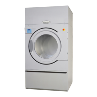
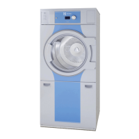
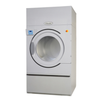
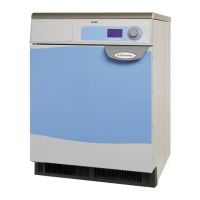
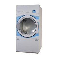
Visual guide identifying key external parts of the tumble dryer, such as the door and drum.
Explains the function of each button and indicator on the manual operational control panel.
Warns about gas ignition failure, error reporting, and the reset procedure.
A guided walkthrough of the entire manual operation process from loading to emptying.
Details the control panel specifically designed for RMC functionality.
Guides on choosing RMC programs (P1, P2, P3) or time-based drying.
Explains the outcomes of RMC programs: Extra Dry (P1), Ready-to-put-away (P2), Ironing-dry (P3).
Identifies and describes the controls for coin-operated tumble dryers.
Guides users through loading, setting temperature, inserting coins, and operating the dryer.
Details the layout and function of controls for machines managed by a central control panel.
Outlines the process of loading, selecting temperature, payment, starting, and stopping the dryer.
Covers daily checks for drum stopping, start interlock, and door seal cleanliness.
Instructions for cleaning the filter compartment without removing the lint filter.
Details checks for air intake, exhaust, and fan wheel cleanliness.
Covers annual checks and states that internal bearings are permanently lubricated.
Provides instructions for cleaning the filter specific to steam heating systems.
Step-by-step instructions for changing the tumble dryer door hinge orientation.
Guidance on unpacking and placing the dryer with necessary clearances for operation and service.
Instructions for adjusting the machine's feet to ensure it stands horizontally and stably.
Details unpacking and positioning for 750/75/650 models.
Ensures adequate fresh air intake for optimal drying, specifying inlet size relative to vent pipe.
Guidance on sizing pipes and fresh-air inlets for multiple machines sharing a common evacuation system.
Explains the air circulation path and recommends design for air evacuation pipes.
Indicates a missing machine type or variety setting, often related to board changes.
Signifies a disconnected thermal sensor, possibly due to a loose or broken connection.
Explains how the 6-digit counter tracks and displays total machine operating hours.
Provides visual dimension sketches and tables for various models and heating types.
Details technical data for Electric and Steam heating on the 300/30 model.
Lists technical data for Gas heating on the 300/30 model, including connections and pressure.
Details technical data for Electric and Steam heating on the 500/50 model.
Lists technical data for Gas heating on the 500/50 model, including connections and pressure.
Details technical data for Electric and Steam heating on the 750/75/650 models.
Lists technical data for Gas heating on the 750/75/650 models, including connections and pressure.
Mandates that electric installation must be carried out by qualified personnel.
Instructions for connecting the power cable to the dryer's terminal strip via cable glands.
Details electric installation for 750/75/650 models, including cable connection and safety switches.
Verification steps for drum rotation, safety interlock, and heating function after installation.
Table providing voltage, heat/motor effect, and fuse ratings for electric heating.
Table showing voltage, total output, and fuse ratings for steam and gas heating.
Table of voltage, heat/motor effect, and fuse ratings for electric heating on 500/50 models.
Table detailing voltage, total output, and fuse ratings for steam/gas heating on 500/50 models.
Table of voltage, total output, and fuse ratings for electric heating in EU/EEA 750/75/650 models.
Table detailing voltage, total output, and fuse ratings for steam/gas heating in EU/EEA 750/75/650 models.
Table of voltage, heat/motor effect, and fuse ratings for electric heating outside EU/EEA.
Table detailing voltage, total output, and fuse ratings for steam/gas heating outside EU/EEA.
Instructions for connecting the main steam pipe, stop cock, dirt collector, and hoses to the battery.
Details installing a water discharger and stop cock for proper condensate return.
Ensures correct hose slope to prevent condensate buildup and recommends pipe insulation.
Details operating pressure and temperature range for water steam used in the system.
Mandates qualified personnel for gas installation and the use of a shut-off valve.
Discusses the gas burner, factory nozzle settings, and requirements for gas type conversion.
Guides on testing gas pressure, flame quality, and nozzle settings after installation.
Details the process for converting the machine to different gas types, including nozzle changes.
Illustrates gas burner components for different model series (300/30, 500/50, 750/75/650).
Identifies key parts of the gas valve assembly, such as nozzle, nipple, and adjusting screw.
Provides pressure and adjustment data for LPG and GNH/GNL gases for English-speaking countries.
Specific pressure and adjustment data for Great Britain and Eire.
Details pressure and adjustment specifications for Propane and GN in Australia and New Zealand.
Explains how to access and use the programming mode to adjust preset machine values.
Stresses that parameter programming must only be performed by qualified personnel.
Guides on switching the control to programming mode via a circuit board switch.
Lists parameters like machine type, temperature, time, cooling, and reversing that can be adjusted.
Explains the usage of SP, Clock, Count Down, and Count Up buttons in programming mode.
Details how to modify the machine type using the control panel buttons.
Presents variants of machine types for different operational modes (manual, coin, CP).
Explains how to select and modify parameter values using the clock and count up/down buttons.
Details settings for temperature programs (High, Medium, Low) and time interval/max running time.
Covers parameters for running time between reversals and temperature hysteresis.
Defines settings for cooling time and residual moisture levels (P1, P2, P3) using hexadecimals.
Details parameters for extra drying time to be added after achieving set moisture levels.
Illustrates how residual moisture is measured and relates it to program stages and drying levels.
Explains the use of hexadecimal notation for residual moisture levels and increment adjustments.
A consolidated table showing factory default values for all adjustable parameters.
| Brand | Electrolux |
|---|---|
| Model | TT300 |
| Category | Dryer |
| Language | English |